

MRI method for measuring velocity profiles in drilling mud
a velocity profile and velocity measurement technology, applied in the direction of magnetic resonance measurement, measurement devices, instruments, etc., can solve the problems of not being able to find an efficient mri method for measuring velocity profiles in drilling, and not being able to make a reliable quantitative prediction of the “visibility” of high shear rate regions at a given field strength, so as to reduce the echo time and reduce the magnetic field strength
Inactive Publication Date: 2017-11-23
ASPECT IMAGING
View PDF1 Cites 0 Cited by
- Summary
- Abstract
- Description
- Claims
- Application Information
AI Technical Summary
Benefits of technology
The present invention introduces an innovative MRI method to measure the velocity profiles in drilling mud. This method achieves this by reducing the echo time by using a specific technique to encode the velocity information into the longitudinal magnetization (Mz) rather than using other techniques that require lowering magnetic field strength. This results in faster and more efficient measurements.
Problems solved by technology
While there is some hope that the problem can be mediated by working at lower magnetic field strengths, there is as yet no way of making a reliable quantitative prediction of the “visibility” of the high shear rate regions at a given field strength.
Thus, finding an efficient MRI method for measuring velocity profiles in drilling mud remains a long-felt but unmet need.
Method used
View moreImage
Smart ImageViewing Examples

Examples
example
[0033]As a demonstration that the method herein disclosed can reproduce results obtained by standard methods, velocity profiles were obtained for glycerol flowing through a 16 mm diameter pipe by the method disclosed in the present invention and by a conventional method. The results are presented graphically in FIG. 3. Open circles indicate the velocity profile obtained by the method herein disclosed, and the velocity profile obtained by a conventional method is indicated by a solid line. As can be seen in the figure, the method disclosed herein accurately reproduces the flow velocity profile obtained by the conventional method, even at the outer edge of the pipe where the velocity approaches zero.
Login to View More PUM
 Abstract
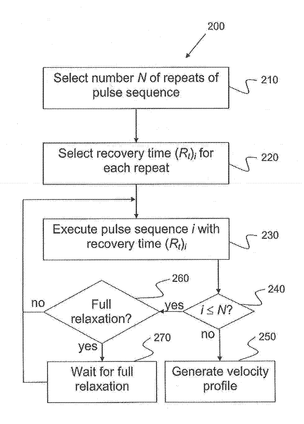
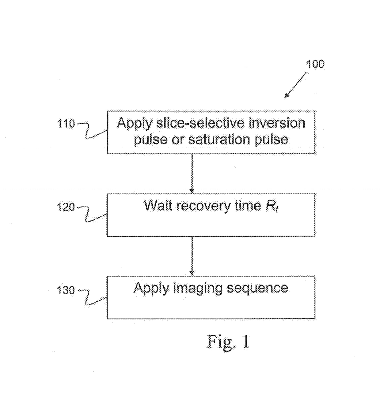
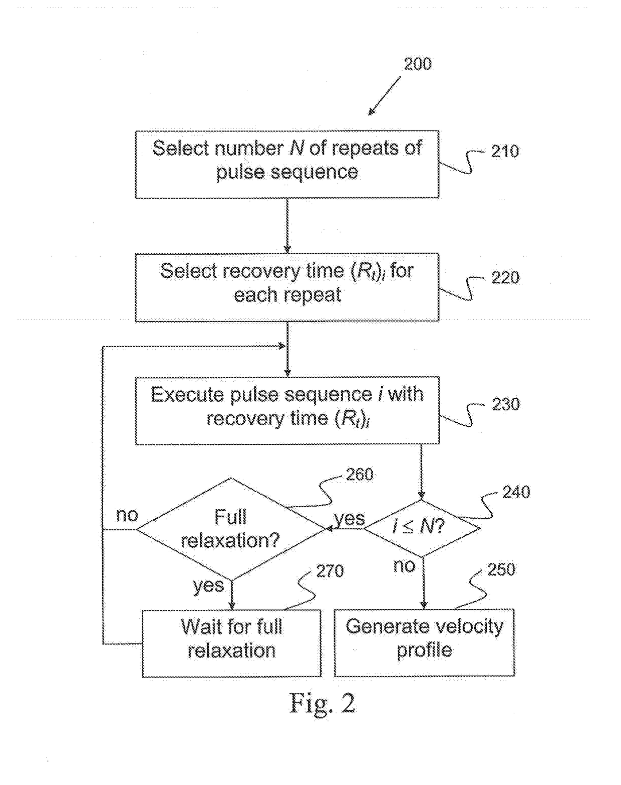
An MRI-based method for determining a velocity profile for a fluid flowing through a pipe, said method comprising: selecting a slice through which said fluid is flowing; selecting a pulse sequence; separating said pulse sequence into a preparation part and a readout part; applying said preparation part to said slice; waiting a predetermined time Rt; and, applying said readout part to said slice.
Description
FIELD OF THE INVENTION[0001]This invention relates to methods for measuring velocity profiles in flows of drilling mud. Specifically, it relates to improved methods that measure the velocity profiles using magnetic resonance imaging (MRI).BACKGROUND OF THE INVENTION[0002]In magnetic resonance imaging (MRI) measurements of certain types of drilling mud, most of the signal is lost from the edges of the pipe, where the velocity is low and the shear rate is high. This loss of signal is evident even in simple spin-echo (SE) images, i.e. images that do not have any velocity-encoding gradients. The degree of signal loss shows a positive correlation with echo time and flow rate.[0003]While there is no definitive proof of the cause of this problem, it appears that it is related to internal gradients in the mud, most likely arising from suspending paramagnetic or magnetic particles in the sample. While there is some hope that the problem can be mediated by working at lower magnetic field stre...
Claims
Login to View More Application Information
Patent Timeline
 Patent Type & AuthorityApplications(United States)
IPC IPC(8): G01R33/563G01R33/483G01R33/48
CPCG01R33/56333G01R33/4835G01R33/4816G01R33/56308
InventorBENDEL, PETERSHAPIRA, BOAZ
OwnerASPECT IMAGING