Control apparatus for ac motor

a control apparatus and motor technology, applied in the direction of electric generator control, dynamo-electric converter control, dynamo-electric gear control, etc., can solve the problems of voltage fluctuation and increase system losses, and achieve the effect of effectively suppressing the fluctuation of output voltage and increasing system losses

Active Publication Date: 2017-10-12
DENSO CORP
View PDF0 Cites 9 Cited by
  • Summary
  • Abstract
  • Description
  • Claims
  • Application Information

AI Technical Summary

Benefits of technology

[0019]In view of the above, with the present invention, when the spectrum amplitude of the bus current at the specific frequency exceeds the judgement threshold value and the converter is in the non-boost state, the voltage command reference value is changed such as to set the converter in the boost state. Thus with the present invention it is possible to effectively suppress fluctuation of the output voltage of the converter, without using the prior art technique of always applying sinusoidal waveform control when the target operating point of the AC motor comes within the LC resonance region of the converter and thereby increasing system losses.

Problems solved by technology

A problem in the prior art is voltage fluctuation that is caused by resonance, when a specific frequency in the amplitude spectrum of the bus current of a converter coincides with the LC resonance frequency of the converter.
With the technique of Japanese Patent No. 5760934, and this may result in increased system losses, since the sine-waveform control method is always applied in such a circumstance.

Method used


Image

  • Control apparatus for ac motor
  • Control apparatus for ac motor
  • Control apparatus for ac motor

Examples


first embodiment

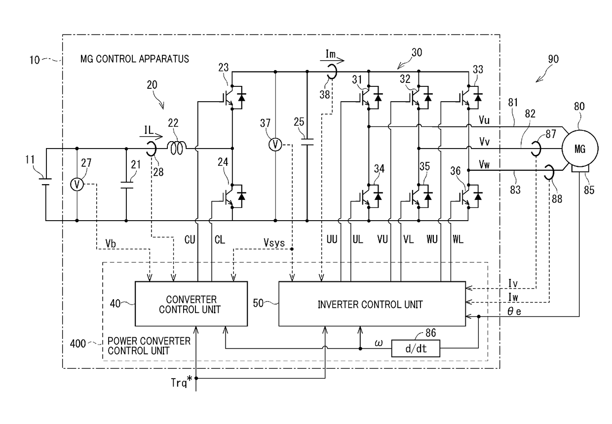
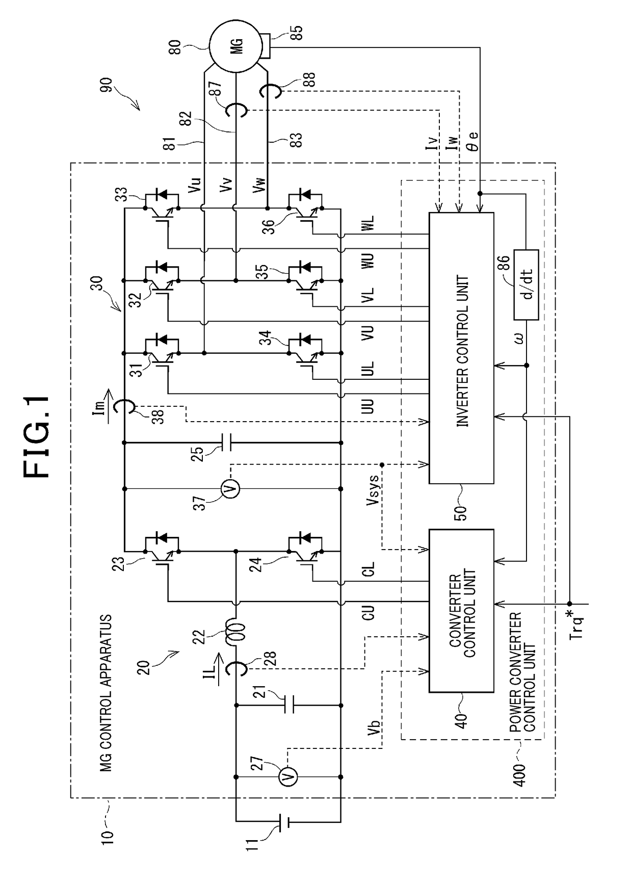
[0105]With the first embodiment, which is a basic example, the boost / non-boost state judgement unit 42 acquires the power source voltage Vb and the voltage command reference value Vsys*. In addition, the detected value of the system voltage Vsys and information on the voltage waveform and the modulation factor m, specified by the modulator 60 of the inverter control unit 50, are acquired, in accordance with the boost / non-boost state judgement configuration.

[0106]The boost / non-boost state judgement unit 42 judges whether the state of the converter 20 required in the next control cycle is to be the boost state or the non-boost state, based on these items of information. Details of the boost / non-boost state judgement configuration are described hereinafter.

[0107]With the present embodiment, as can be understood by referring to FIG. 8, the “boost state” of the converter 20 signifies “a state in which the the high-potential side switching element 23 is continuously switched alternately t...

second embodiment

[0132]With the second embodiment, the system voltage Vsys is used as information acquired by the boost / non-boost state judgement unit 42, as indicated by a single-dot chain line in FIG. 6.

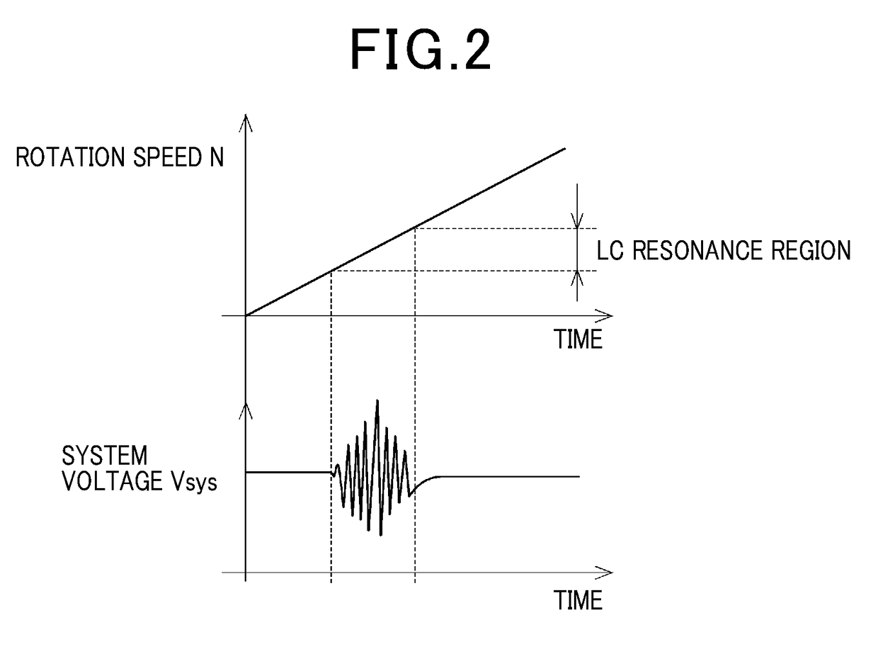
[0133]With the second embodiment as shown in FIG. 9A, a threshold value Vsys_th is set for the system voltage Vsys. The boost state / non-boost state judgement unit 42 acquires the detected value of the system voltage Vsys, detected by the voltage sensor 37. In FIG. 9A prior to time tx, in the boost state, the system voltage Vsys is higher than the threshold value Vsys_th. Subsequently when the system voltage Vsys falls below the threshold value Vsys_th at time tx, the boost / non-boost state judgement unit 42 determines that a request for transition from the boost state to the non-boost state has occurred, and notifies this to the voltage command value alteration unit 43.

[0134]If the spectrum amplitude of the bus current at the specific frequency is equal to or higher than the judgement threshold valu...

third embodiment

[0135]With the third embodiment as shown in FIG. 9B, a threshold value Vsys*_th is set for the voltage command reference value Vsys*.

[0136]The boost state / non-boost state judgement unit 42 acquires the voltage command reference value Vsys* calculated by the voltage command reference value calculation unit 41. In FIG. 9B, prior to time tx, in the boost state, the voltage command reference value Vsys* is higher than the threshold value Vsys*_th. Subsequently when the voltage command reference value Vsys* falls below the threshold value Vsys*_th, at time tx, the boost / non-boost state judgement unit 42 judges that there is a request for transition from the boost state to the non-boost state, and notifies this to the voltage command value alteration unit 43.

[0137]If the spectrum amplitude of the bus current at the specific frequency is equal to or greater than the judgement threshold value at this time, the voltage command value alteration unit 43 changes the voltage command reference va...


PUM


Abstract

In a control apparatus for an AC motor, a voltage waveform specifying unit of an inverter control unit specifies a voltage waveform for operating the inverter, based on a voltage vector calculated by a voltage command calculation unit. A spectrum amplitude extraction unit acquires values of bus current of the inverter and extracts the spectrum amplitude of the specific frequency that corresponds to the LC resonance frequency of the converter. A boost/non-boost state judgement unit of a converter control unit determines whether the state required by the converter in the next control cycle is the boost state or the non-boost state. When the spectrum amplitude of the specific frequency, correlated with the voltage waveform, is higher than the judgement threshold value and the converter is in the non-boost state, a voltage command value alteration unit changes the voltage command reference value such that the converter transitions to the boost state.

Description

CROSS-REFERENCE TO RELATED APPLICATION[0001]This application is based on and claims the benefit of priority from earlier Japanese Patent Application No. 2016-79533 filed Apr. 12, 2016, the descriptions of which are incorporated herein by reference.BACKGROUNDTechnical Field[0002]The present invention relates to a control apparatus for an AC motor, provided with a converter capable of boosting a power source voltage.Related Art[0003]Types of control apparatus for an AC motor are known in the prior art, where the control apparatus is provided with a converter that boosts a power source voltage by energy from a reactor, with a capacitor being charged to the boosted supply voltage. Furthermore a technique is known whereby the method of controlling the inverter is switched if the target operating point of the AC motor comes within the LC resonance region of the converter.[0004]For example with the drive apparatus disclosed in Japanese Patent No. 5760934, when the target operating point of...

Claims


Application Information

Patent Timeline
Patent Type & Authority Applications(United States)
IPC IPC(8): H02P27/08H02P21/22B60L50/13
CPCH02P27/08H02M7/53871B60L11/08H02P21/22B60L50/13H02M1/44H02M3/1588H02P27/06H02P2201/07H02M1/007H02M7/53876Y02B70/10
Inventor TAKAHASHI, HIDEKAZU
Owner DENSO CORP
Why Eureka
Try Eureka