
Method and system for decoding a modulated signal

a modulated signal and modulation technology, applied in the field of modulated signal decoding methods and systems, can solve the problems of inability to detect differential phase angles correctly any longer, inability to achieve perfect frequency offset in practice, and up to 400 seconds for full local oscillator laser scan

Active Publication Date: 2017-10-12
XIEON NETWORKS SARL
View PDF4 Cites 2 Cited by
  • Summary
  • Abstract
  • Description
  • Claims
  • Application Information

AI Technical Summary

Benefits of technology

This patent is about a new method for decoding optical signals that allows for faster and more reliable decoding even when there are significant frequency offsets between the local oscillator laser and the center frequency of the incoming optical signal. By using multiple decoding rules that are tested in parallel, the method can accommodate different frequencies and is more efficient and cost-effective. This new method can be implemented both sequentially and simultaneously, and can allow for faster processing and longer distance communication without the need for expensive and precise laser equipment.

Problems solved by technology

Due to imperfections in the electronic equipment and the limited frequency stability of the local oscillator laser, a perfect frequency offset can hardly be achieved in practice, neither in intradyne detection nor in heterodyne detection.
If the frequency offset is too large, the differential phase angles cannot be detected correctly any longer.
Assuming that a laser scans 100 steps per second, a full local oscillator laser scan can take up to 400 seconds, which is an unacceptably long time interval for many practical applications.
However, these schemes introduce additional complexities.

Method used


Image

  • Method and system for decoding a modulated signal
  • Method and system for decoding a modulated signal
  • Method and system for decoding a modulated signal

Examples


Embodiment Construction

[0043]The features and numerous advantages of the method and system for decoding a modulated signal according to the present invention will be best apparent from a detailed description of preferred embodiments with reference to the accompanying drawings, in which:

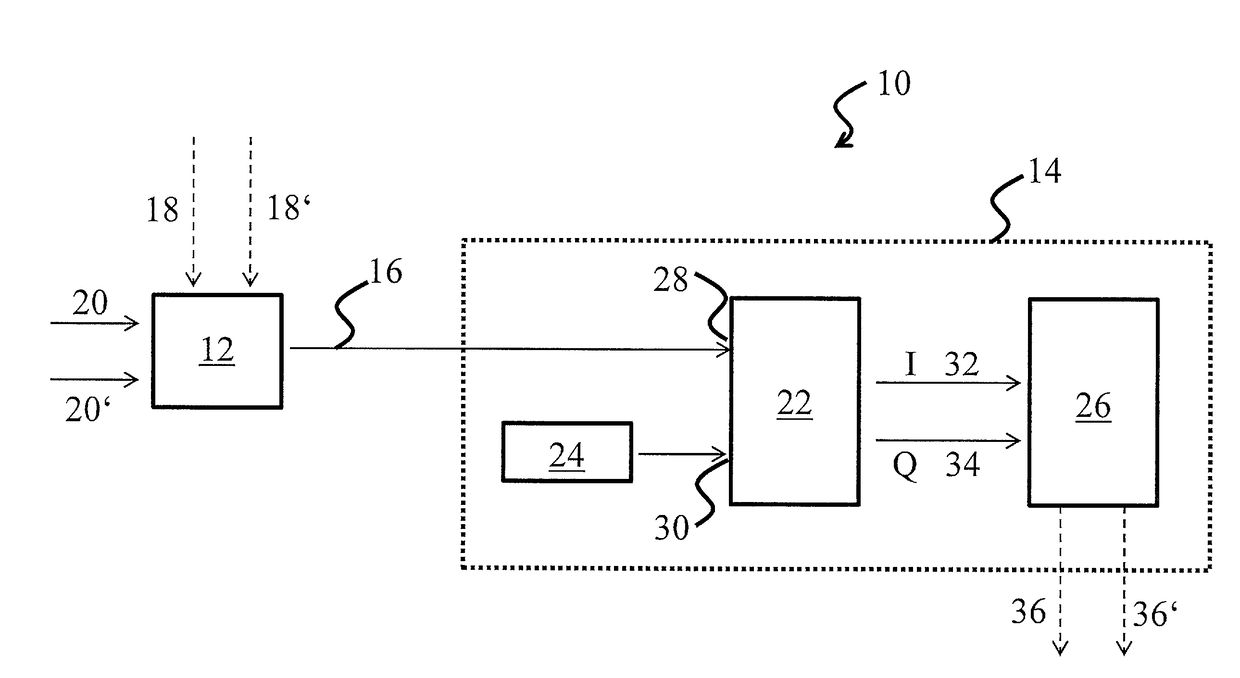
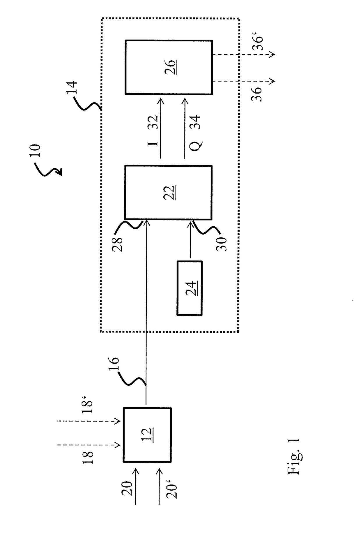
[0044]FIG. 1 is a schematic view of a system for transmitting a modulated signal which comprises a system for decoding the signal according to an embodiment of the present invention;

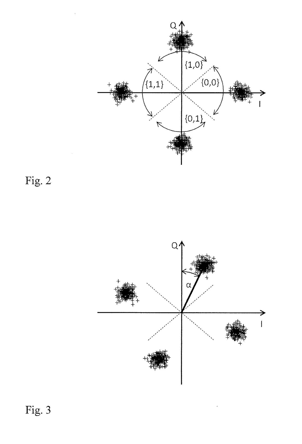
[0045]FIG. 2 is a schematic constellation diagram for an example in which two bits per symbol are transmitted, and with perfect frequency compensation;

[0046]FIG. 3 is a rotated constellation diagram that corresponds to an imperfect frequency compensation; and

[0047]FIG. 4 is a schematic diagram of a decoding system according to an embodiment of the present invention.

[0048]FIG. 1 is a schematic diagram of a system 10 for transmitting a quadrature amplitude modulated signal between a sender unit 12 and a receiver unit 14 over an optical channel 16,...


PUM


Abstract

In a method and system for decoding a differential M-ary phase or quadrature amplitude modulated signal, the incoming signal is decoded according to a plurality of different decoding rules, wherein said plurality of decoding rules correspond to different values of a resulting frequency difference or mismatch between a signal frequency and a local oscillator reference frequency. The invention allows to increase a tolerance window for the maximal allowable frequency offset, and thus helps to speed up an initial locking process or to allow for equipment which has a lower tuning granularity.

Description

FIELD OF THE INVENTION[0001]The invention relates to an improved method and system for decoding a modulated signal, in particular a coherently received and decoded differential M-ary phase or quadrature ampli-tude-modulated optical signal.BACKGROUND OF THE INVENTION[0002]In a coherent optical reception of differential M-ary phase-modulated signals, the incoming optical signal at some given frequency is non-linearly mixed (or superimposed) with a reference local oscillator that is set at a close-by frequency. The desired outcome is a mixing signal at the difference frequency, which carries the information (such as amplitude, phase, and frequency modulation) of the original higher frequency signal in the phase angle, but is oscillating at a lower, and hence more easily processed frequency.[0003]The detected phase angle depends on two factors: the transmitted (sent) symbol and the frequency offset between the local oscillator laser and the center frequency of the incoming optical signa...

Claims


Application Information

Patent Timeline
IPC IPC(8): H04B10/63H04B10/61H04L27/26
CPCH04B10/63H04B10/611H04B10/612H04L27/2647H04L27/227H04L27/3818H04L27/2071H04L27/362H04L2027/0065H04L2027/0026H04B10/65
Inventor ROHDE, HARALD
Owner XIEON NETWORKS SARL
Learn More