Detection and reconstruction of pitch rate sensor fault

Active Publication Date: 2017-10-19
GM GLOBAL TECH OPERATIONS LLC
View PDF3 Cites 4 Cited by
  • Summary
  • Abstract
  • Description
  • Claims
  • Application Information

AI Technical Summary

Benefits of technology

[0004]An advantage of an embodiment is a detection of the fault of a pitch sensor and reconstruction of the faulted signal by combining vehicle kinematic and dynamic models with unknown input observers and estimated vehicle states to detect and reconstruct the faults. Robustness to road grade and road bank disturbances is an advantage of the proposed structure. The technique described herein utilizes a model, observer, and adaptive fault t

Problems solved by technology

When the sensors are utilized to sense for conditions that contribute to the instability, such sensors are often considered critical.
As a result, it must be known when these sensors become faulty.
Although hardware redundancy (i.e

Method used


Image

  • Detection and reconstruction of pitch rate sensor fault
  • Detection and reconstruction of pitch rate sensor fault
  • Detection and reconstruction of pitch rate sensor fault

Examples


Example

[0021]The following detailed description is meant to be illustrative in understanding the subject matter of the embodiments and is not intended to limit the embodiments of the subject matter or the application and the uses of such embodiments. Any use of the word “exemplary” is intended to be interpreted as “serving as an example, instance, or illustration.” Implementations set forth herein are exemplary are not meant to be construed as preferred or advantageous over other implementations. The descriptions herein are not meant to be bound by any expressed or implied theory presented in the preceding background, detailed description or descriptions, brief summary or the following detailed description.

[0022]Techniques and technologies may be described herein in terms of functional and / or logical block components, and with reference to symbolic representations of operations, processing tasks, and functions that may be performed by various computing components or devices. Such operation...


PUM


Abstract

A method of reconstructing a detected faulty signal. A pitch sensor fault is detected by a processor. A signal of the detected faulty pitch sensor is reconstructed using indirect sensor data. The reconstructed signal is output to a controller to maintain stability.

Description

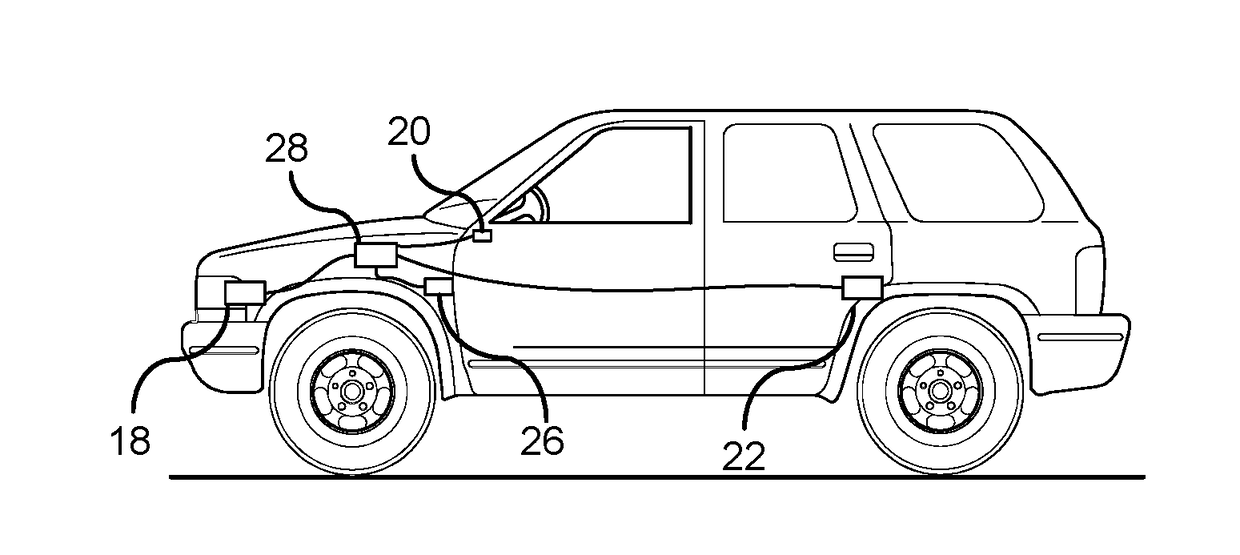
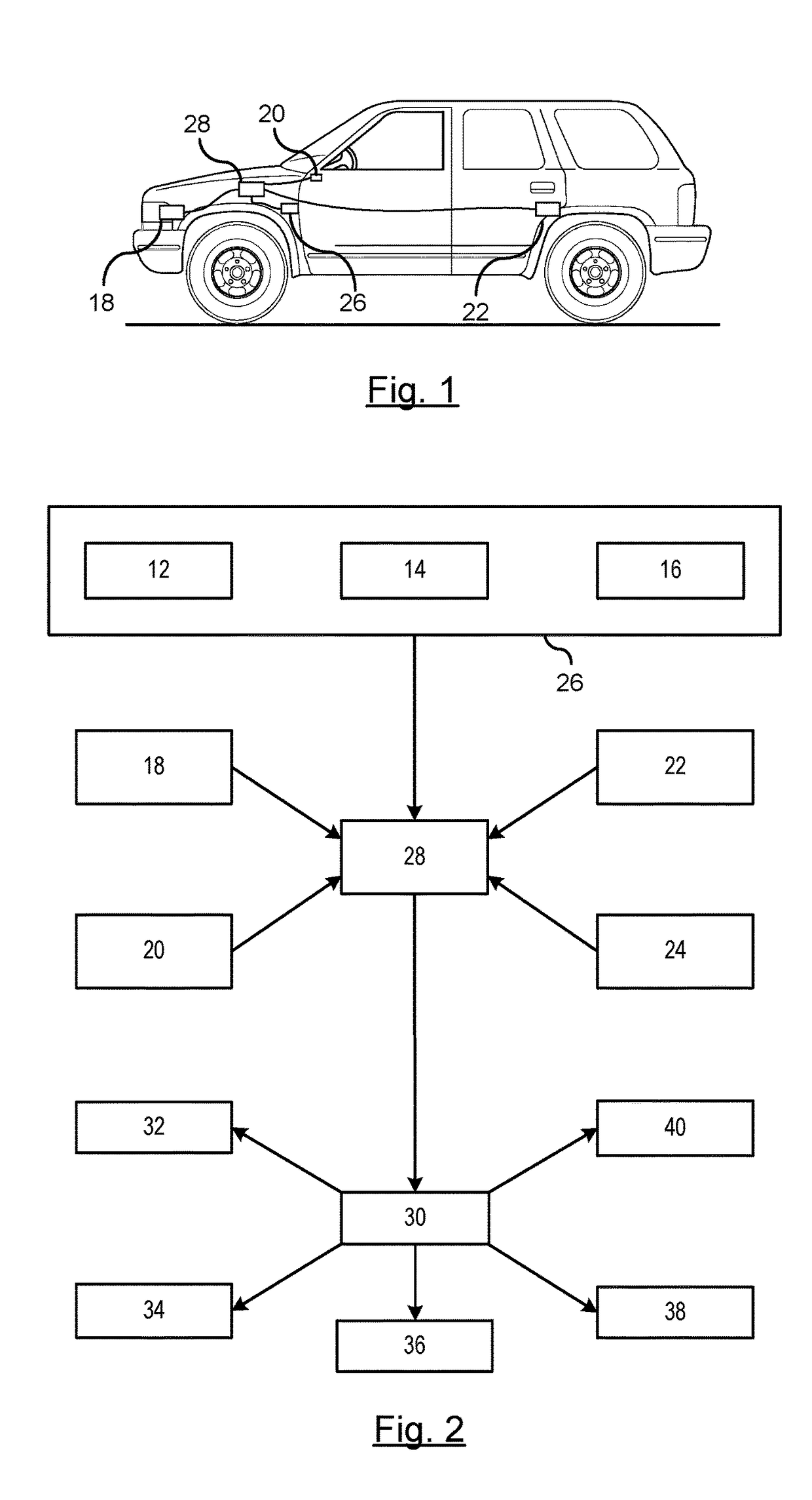
BACKGROUND OF INVENTION[0001]An embodiment relates to state of detecting sensor faults and correcting sensor signals.[0002]Diagnostic monitoring of vehicle stability systems includes a variety of sensors monitoring various dynamic conditions of the vehicle. Such systems employ various types of sensors for identifying when a status condition of an operation. For example, rollover stability control systems utilize roll rate sensors and pitch rate sensors for detecting a vehicle's instability. In response to detecting the vehicle's instability, corrective actions may be deployed by a vehicle stability control system by actuating one or more vehicle operations (e.g., driving, braking, speed control) to counter the instability condition.[0003]When the sensors are utilized to sense for conditions that contribute to the instability, such sensors are often considered critical. As a result, it must be known when these sensors become faulty. Typically, to assure continued operation of the fun...

Claims


Application Information

Patent Timeline
IPC IPC(8): B60W50/02B60W30/02B62D15/02B60T8/1755
CPCB60W50/0205B60W30/02B60W2050/0215B62D15/025B60T8/1755G01D18/00B60W50/0225B60T8/172B60T8/17551B60T2250/06B60T2270/413B60W2510/22B60W2520/14B60W2520/16B60W2520/18B60W2520/28B60W2540/18G01D3/022B60T2230/02B60T8/17552
Inventor CHEN, SHIH-KENLITKOUHI, BAKHTIAR B.KHAJEPOUR, AMIRZARRINGHALAM, REZAMELEK, WILLIAM
Owner GM GLOBAL TECH OPERATIONS LLC
Why Eureka
Try Eureka