Self-lubricating roller bearing and methods of making and using self-lubricating roller bearing

a self-lubricating roller bearing and self-lubricating technology, applied in the field of bearings, can solve problems such as failure of roller bearings

Inactive Publication Date: 2017-10-19
CATERPILLAR INC
View PDF11 Cites 7 Cited by
  • Summary
  • Abstract
  • Description
  • Claims
  • Application Information

AI Technical Summary

Benefits of technology

[0005]In one aspect of the present disclosure, a self-lubricating additive manufactured steel roller bearing is provided. The roller bearing includes an additive manufactured steel inner race, an additive manufactured steel outer race, and a plurality of additive manufactured steel rollers contacting the inner and outer races and arranged in a space between the inner and outer races. Each of the inner race and the outer race includes a bearing surface facing the space, where the bearing surface includes a plurality of laser hardened areas arranged in a predetermined pattern and a non-laser hardened area having respective portions separating adjacent laser hardened areas of the predetermined pattern. The laser hardened areas are harder than the non-laser hardened area. Further, the laser hardened areas extend a predetermined depth from the bearing surface, the predetermined depth being less than a maximum depth by which the non-laser hardened area extends from the bearing surface. The non-laser hardened area is a sacrificial bearing surface that creates a dry lubricant upon wear of the non-laser hardened area, and the laser hardened areas are load bearing portions of the roller bearing. The laser hardened areas have a metal infiltrated lattice structure, particularly a bronze infiltrated lattice structure according to one or more embodiments of the disclosed subjected matter.

Problems solved by technology

During operation of the roller bearings, i.e., during relative movement of the inner race with respect to the outer race, contact surfaces of the inner race, the outer race and the rolling elements can experience continuous fatigue load, which can cause wear of the contact surfaces and may ultimately lead to failure of the roller bearing.
In such a case, the service life of the roller bearing may be dependent upon the amount or type of lubrication initially provided, since lubricant replenishment after initial assembly of the roller bearing may not be practical or possible.

Method used


Image

  • Self-lubricating roller bearing and methods of making and using self-lubricating roller bearing
  • Self-lubricating roller bearing and methods of making and using self-lubricating roller bearing
  • Self-lubricating roller bearing and methods of making and using self-lubricating roller bearing

Examples


Embodiment Construction

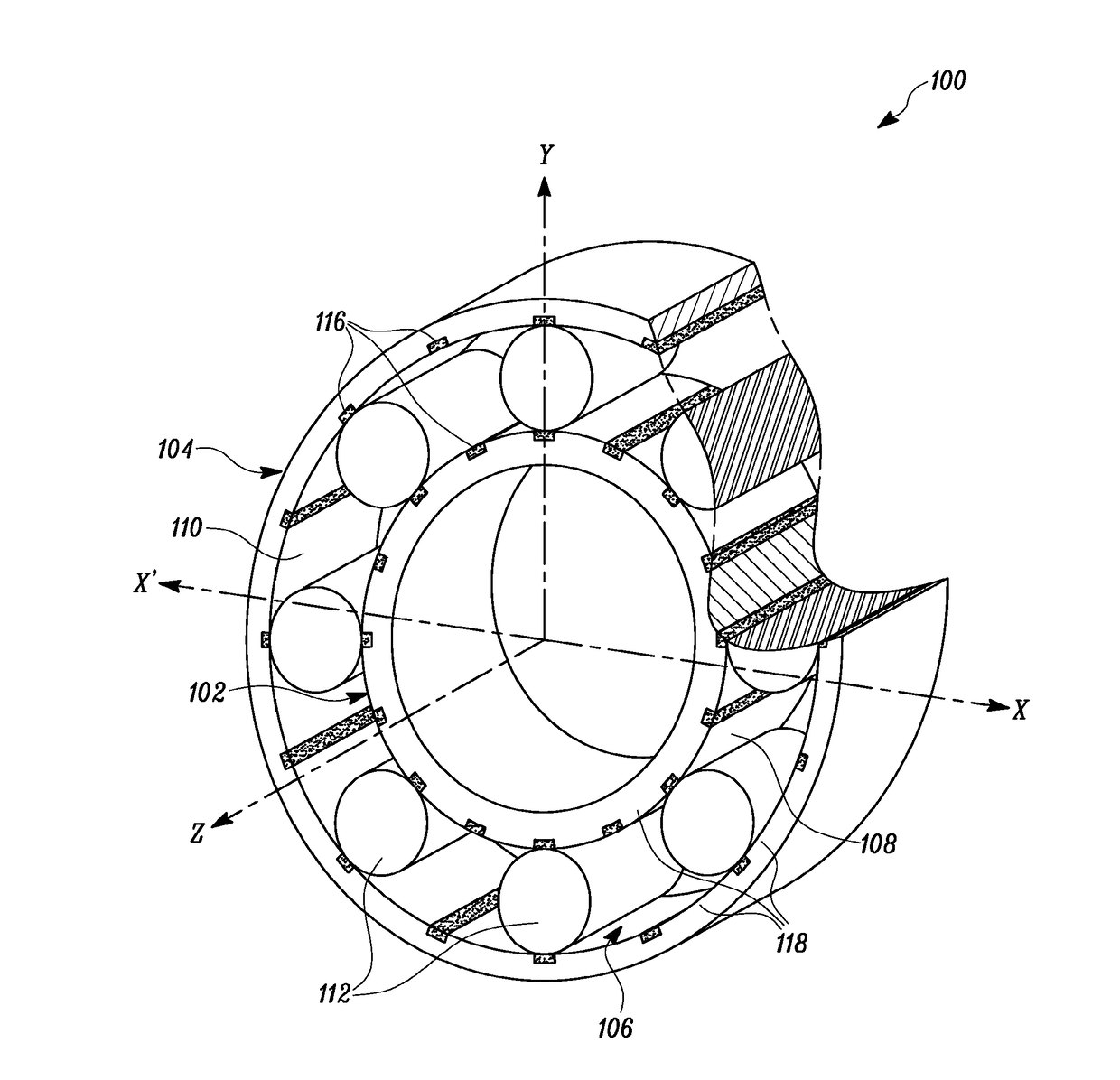
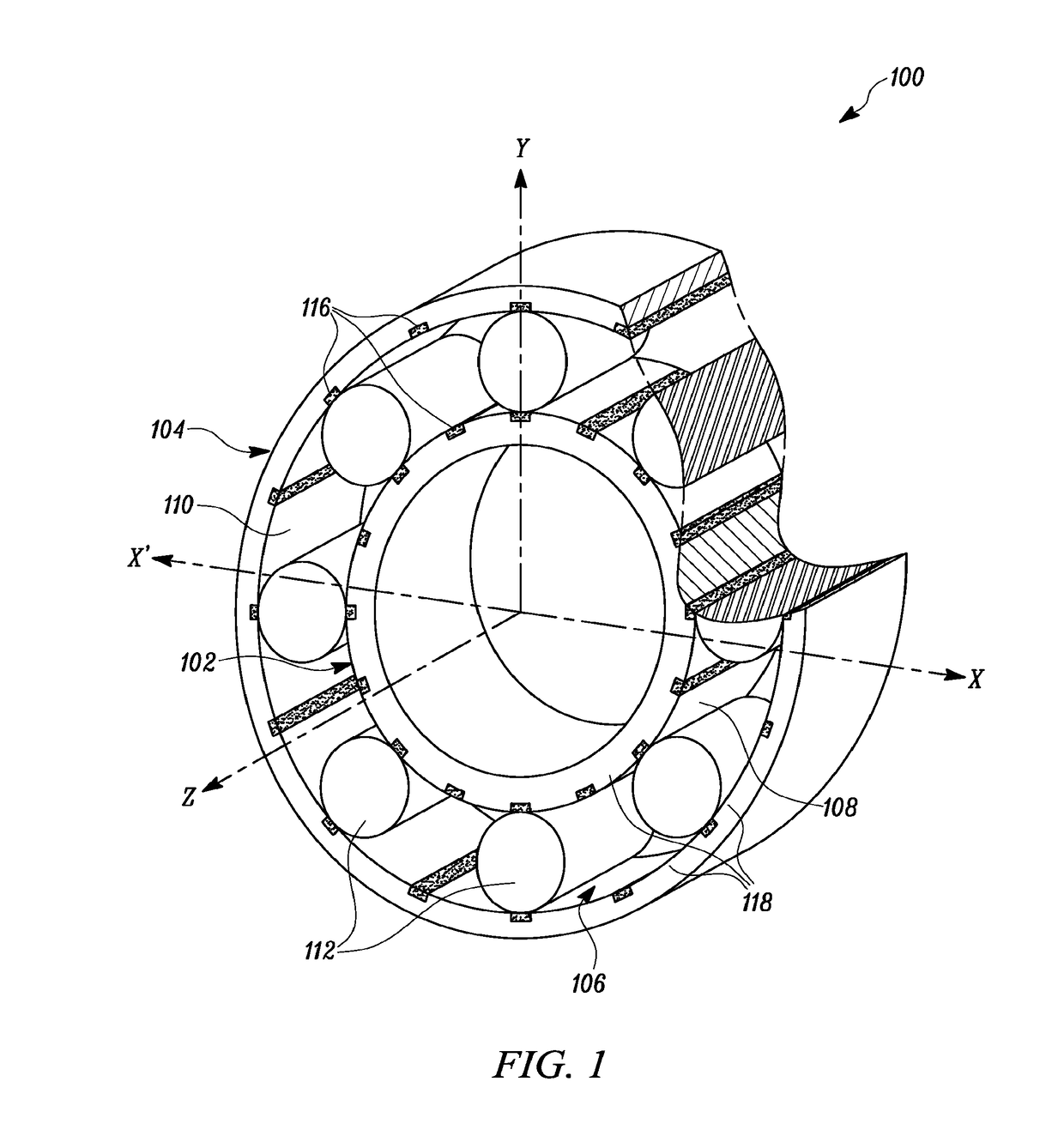
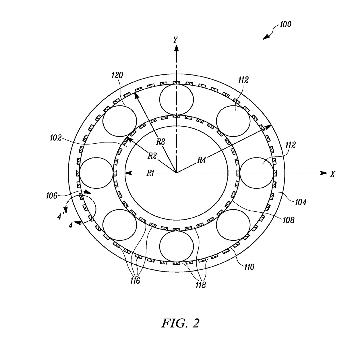
[0019]The description set forth below in connection with the appended drawings is intended as a description of various embodiments of the described subject matter and is not necessarily intended to represent the only embodiment(s). In certain instances, the description includes specific details for the purpose of providing an understanding of the described subject matter. However, it will be apparent to those skilled in the art that embodiments may be practiced without these specific details. In some instances, well-known structures and components may be shown in block diagram form in order to avoid obscuring the concepts of the described subject matter. Wherever possible, corresponding or similar reference numbers will be used throughout the drawings to refer to the same or corresponding parts.

[0020]Any reference in the specification to “one embodiment” or “an embodiment” means that a particular feature, structure, characteristic, operation, or function described in connection with...


PUM

PropertyMeasurementUnit
depthaaaaaaaaaa
lattice structureaaaaaaaaaa
surface areaaaaaaaaaaa

Abstract

A self-lubricating roller bearing is provided. The roller bearing includes an inner race, an outer race, and a plurality of rollers between the inner and outer races. Each of the inner race and the outer race includes a bearing surface for contact with the rollers. The bearing surface of one or more of the inner race, the outer race, and the rollers has one or more laser hardened areas and one or more non-laser hardened areas arranged in a predetermined pattern. The one or more non-laser hardened areas create dry lubricant for the roller bearing upon wear thereof.

Description

TECHNICAL FIELD[0001]The present disclosure generally relates to bearings, and more particularly to self-lubricating roller bearings and methods of making and using self-lubricating roller bearings.BACKGROUND[0002]Roller bearings are often used with rotating elements of machines, such as vehicles, turbines, pumps and the like. Roller bearings support rotating elements while also constraining relative motion of rotating elements. Typically, a roller bearing includes an inner race and an outer race concentric with the inner race. In a space defined between the inner race and the outer race, a set of rolling elements or rollers is provided. The rolling elements facilitate relative movement between the inner race and the outer race. During operation of the roller bearings, i.e., during relative movement of the inner race with respect to the outer race, contact surfaces of the inner race, the outer race and the rolling elements can experience continuous fatigue load, which can cause wear...

Claims


Application Information

Patent Timeline
Patent Type & Authority Applications(United States)
IPC IPC(8): F16C33/66B22F3/105F16C33/64B22F5/10F16C33/34B33Y10/00B33Y80/00
CPCF16C33/6696F16C33/34F16C33/64B33Y10/00B22F5/106F16C2220/20B33Y80/00B22F3/1055F16C19/26F16C2223/10F16C2206/06F16C2220/24Y02P10/25B22F10/28
Inventor LOZIER, RYAN A.MARCHIONE, THIERRY A.
Owner CATERPILLAR INC
Why Eureka
Try Eureka