Safety Overload for Direct Skeletal Attachment

a safety overload and skeletal technology, applied in the field of direct skeletal attachment safety overload, can solve the problems of less satisfactory functional outcome of a prosthesis, compromise of prosthesis control, and difficulty in achieving the effect of ensuring the safety of the skeletal attachmen

Active Publication Date: 2017-10-26
REHABILITATION INST OF CHICAGO
View PDF11 Cites 6 Cited by
  • Summary
  • Abstract
  • Description
  • Claims
  • Application Information

AI Technical Summary

Problems solved by technology

As a general rule, the higher the level of transfemoral amputation, the less satisfactory the functional outcome with a prosthesis because the patient loses musculature to control the femur.
Though this is a standard care option, many drawbacks exist, including skin-related issues (e.g., blisters, cysts, skin irritation), and compromised control of the prosthesis.
Despite numerous advantages of the procedure, challenges still remain.
These challenges include infection, bone loss, bone fractures, loosening of hardware, and breakage of percutaneous parts.
The stiffness of a titanium implant is much higher than that of the surrounding compact bone, so there is a potential for bone fracture near the osteotomy due to a high external load (e.g., a fall scenario).
The area above the implant is most susceptible to fracture, and there is also a risk of longitudinal bone fracture along the length of the implant.

Method used


Image

  • Safety Overload for Direct Skeletal Attachment
  • Safety Overload for Direct Skeletal Attachment
  • Safety Overload for Direct Skeletal Attachment

Examples


Embodiment Construction

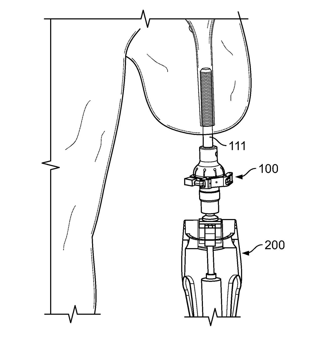
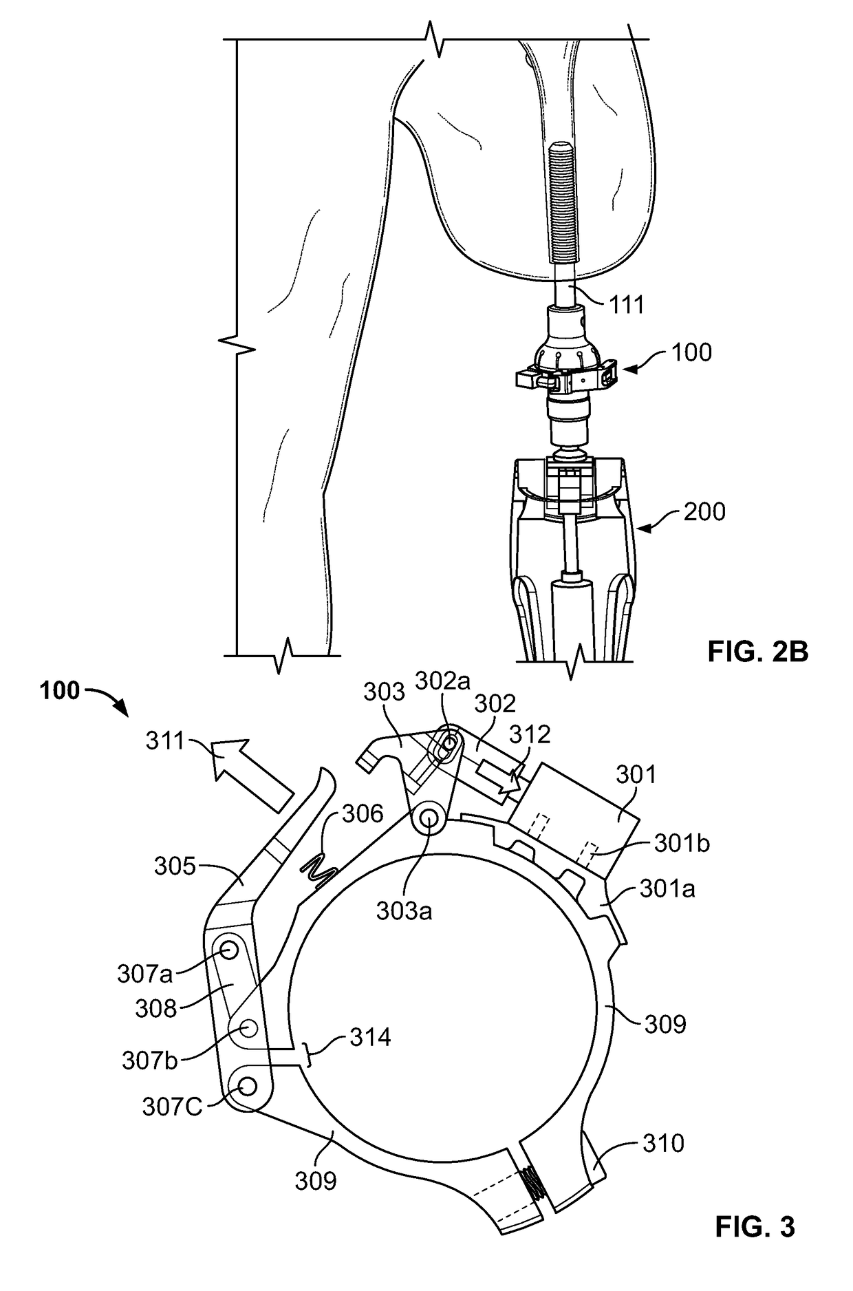
[0023]An embodiment discloses a safety mechanism, referred to herein as an “overload device” or simply as a “device”, to be used with artificial limbs that attach directly to the skeletal system. The overload device may be used to assist persons with transfemoral amputation. One benefit of embodiments disclosed herein is improve the safety of bone-anchored prostheses for individuals with transfemoral amputations.

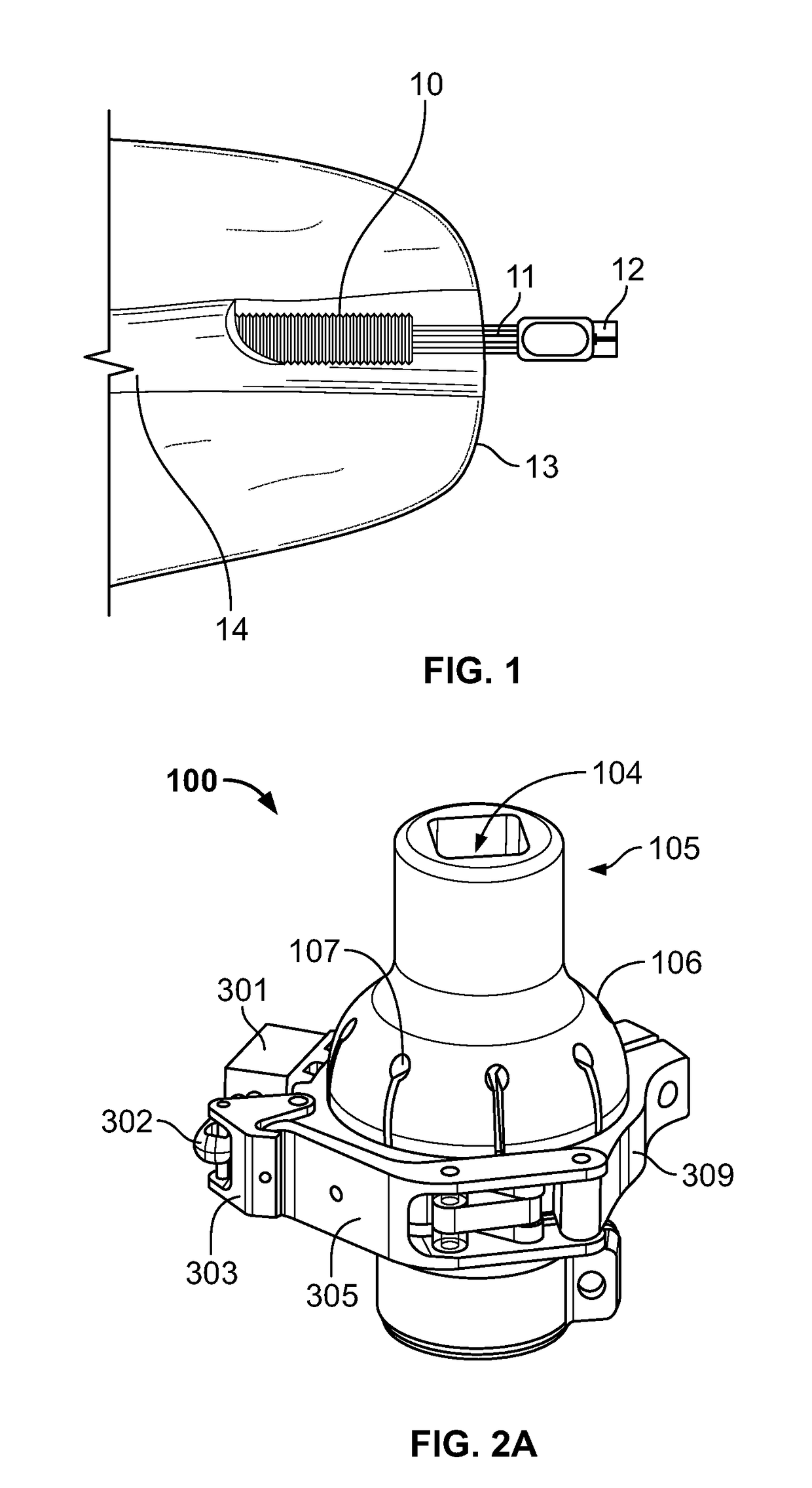
[0024]FIG. 1 shows a view of an osseointegrated implant system, comprising fixture 10, abutment 11, abutment screw 12, skin 13, and bone 14. In various embodiments, systems and methods are disclosed that can prevent overloading of the bone and implant for prostheses that are attached directly to the skeletal system. In an embodiment, such systems and methods may be used in connection with an OPRA implant system, which it is a threaded implant that is potentially susceptible to torsion and loosening.

[0025]In an embodiment, an overload device functions as a fail-safe mechanism...


PUM


Abstract

Systems and methods are disclosed for prosthetic devices. In one embodiment, an apparatus comprises a first section attachable to an abutment screw of a percutaneous implant; a second section attachable to a prosthetic limb; a latch for coupling the first section with the second section, the latch releasable in response to an overload on the prosthetic limb. A compliance component may be positioned between the first section and the second section, such that when the latch releases in response to the overload, the compliance component provides a tension between the first section and the second section.

Description

RELATED APPLICATIONS[0001]This application claims benefit to U.S. Provisional Patent Application 62 / 326,418 filed on Apr. 22, 2017, which is incorporated by reference.FEDERALLY SPONSORED RESEARCH OR DEVELOPMENT[0002][Not Applicable]MICROFICHE / COPYRIGHT REFERENCE[0003][Not Applicable]BACKGROUND OF THE INVENTION[0004]Amputation is the surgical removal of part or all of a limb to address trauma, tumor, disease, and congenital defects. The surgeon must find a balance between two main goals: removal of the diseased or damaged portion of the limb, and reconstruction of the remaining, or residual, limb to promote healing and maintain functionality of the limb. Amputation of the lower limb is the most prevalent major amputation surgery. As of 2005, there were 623,000 Americans living with lower limb amputations, either above or below knee. Most lower limb amputations are a consequence of disease; however, trauma and cancer are significant etiologies and account for 19% of the population.[00...

Claims


Application Information

Patent Timeline
Patent Type & Authority Applications(United States)
IPC IPC(8): A61F2/80A61F2/64A61F2/54A61F2/50A61F2/78
CPCA61F2/80A61F2/54A61F2002/5073A61F2002/7887A61F2002/5003A61F2/64A61F2/78A61F2002/5083
Inventor KUIKEN, TODDPESHKIN, MICHAELKAVENY, KYLE
Owner REHABILITATION INST OF CHICAGO
Why Eureka
Try Eureka