Xylene Separation Process

a technology of paraxylene and separation process, which is applied in the field of paraxylene separation process, can solve the problems of increasing cost and energy consumption, accelerating wear and tear of peripheral equipment, etc., and achieves the effect of increasing the separation rate, and reducing the size and complexity of peripheral equipmen

Inactive Publication Date: 2017-10-26
EXXONMOBIL CHEM PAT INC
View PDF5 Cites 5 Cited by
  • Summary
  • Abstract
  • Description
  • Claims
  • Application Information

AI Technical Summary

Benefits of technology

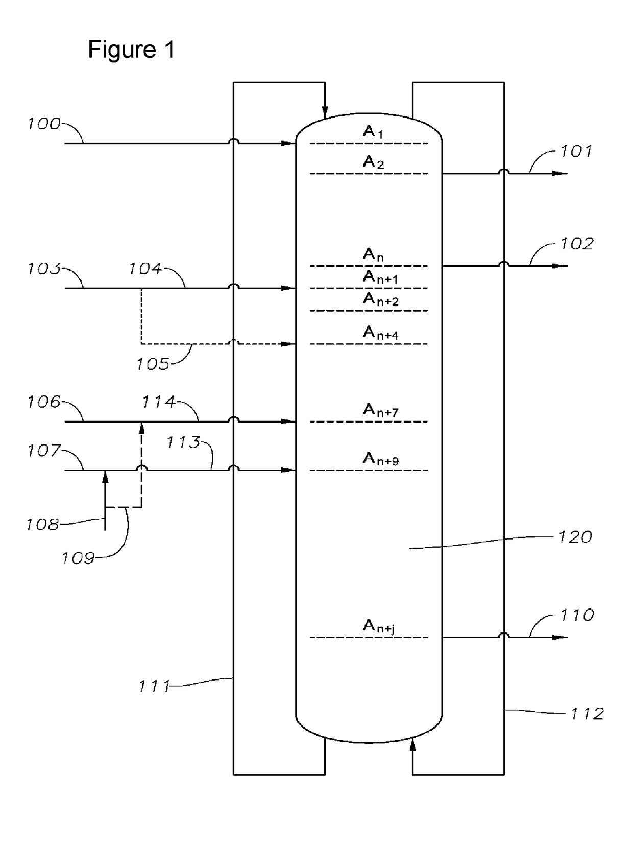
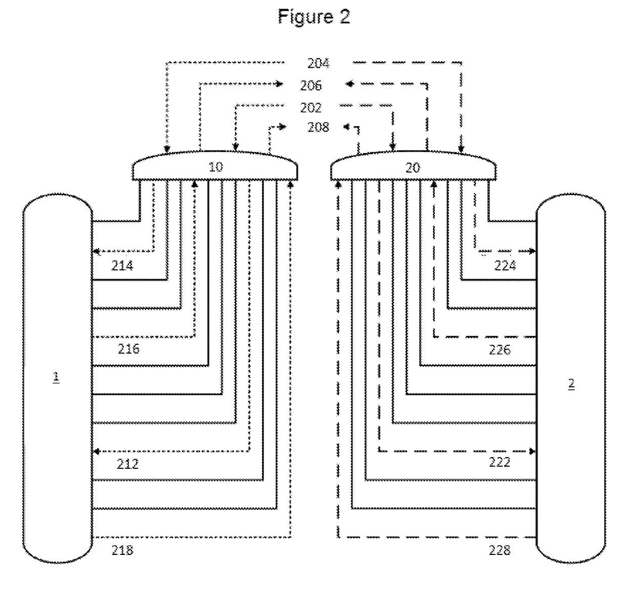
[0011]Embodiments disclosed herein are directed to using an improved PowerFeed process to separate a C8 aromatic, such as paraxylene or ethylbenzene, from a mixture of C8 aromatics in a simulated moving bed adsorption apparatus having at least two sieve chambers and at least two rotary valves. The use of PowerFeed significantly enhances the separation of paraxylene (or other desired C8 aromatic). When a simulated moving bed adsorption apparatus having two or more sieve chambers and two or more rotary valves is used, each sieve chamber may be operated individually, i.e., as two or more independent simulated moving bed units rather than a collective unit, using the PowerFeed process. Managing the PowerFeed process in each chamber such that a substantially constant flow rate of streams to or from the apparatus is achieved minimizes the size and complexity of the peripheral equipment, e.g., pumps, surge vessels, heat exchangers, conduits for transferring streams to and from the rotary valves, etc. Accordingly, the present invention reduces operation cost and energy consumption and prolongs the life cycle of the apparatus as compared to PowerFeed processes described in prior art. Embodiments disclosed herein allow for upgrading an existing simulated moving bed apparatus to use the PowerFeed process with minimized capital investment.

Problems solved by technology

A challenge of using a PowerFeed process is that it requires larger and higher capacity peripheral equipment, such as attendant distillation towers, pumps, surge vessels, and heat exchangers, in order to handle the cyclic flows and much higher peak flow rate of streams as compared with a non-PowerFeed process where the flow rates remain constant, increasing cost and energy consumption.
In addition, a PowerFeed process may have a high frequency of flow variation, which can accelerate wear and tear of peripheral equipment.

Method used


Image

  • Xylene Separation Process
  • Xylene Separation Process
  • Xylene Separation Process

Examples


example 2 (

Inventive)

[0093]In this inventive example, the objective function is to maximize FFeed, the feed flow rate. The flow rates and results for the simulation of Example 2 are shown in Table 3.

TABLE 30 - X / 2X / 2 - XOperatingCham-Cham-To-Cham-Cham-To-conditionsber Aber Btalber Aber BtalFeed sub-stream06.116.116.1106.11flow rate (m3 / min)Desorbent sub-4.882.457.332.454.887.33stream flow rate(m3 / min)Extract sub-stream05.85.85.805.8flow rate (m3 / min)Raffinate sub-stream4.882.777.652.774.887.65flow rate (m3 / min)SMB Performance parametersThroughput6.12(m3 / min)Ratio of Desorbent1.2to Feed flow rate

[0094]This simulation shows that for an optimized simulated moving bed unit, with two sieve chambers each having 12 beds, operated independently and with PowerFeed, the combined throughput is 6.2 m3 / min. Thus, the two-chamber configuration is able to achieve a 60% improvement in the throughput, while using the same desorbent to feed ratio of 1.2. The total flow, which is the sum of the flows from both c...

example 4 (

Inventive)

[0097]In this inventive example, the objective function is to minimize the amount of desorbent being used, while maintaining a fixed throughput of 3.8 m3 / min. The flow rates and results for the simulation of Example 4 are shown in Table 5. Zone 1 flow rate refers to the sum of flow rates of the recycled flow from the last bed and the desorbent.

TABLE 50 - X / 2X / 2 - XOperatingCham-Cham-To-Cham-Cham-To-conditionsber Aber Btalber Aber BtalZone 1 flow rate3.373.236.63.233.376.6(m3 / min)Feed sub-stream2.281.523.81.522.283.8flow rate (m3 / min)Desorbent sub-0.31.681.981.680.31.98stream flow rate(m3 / min)Extract sub-stream1.3901.3901.391.39flow rate (m3 / min)Raffinate sub-stream1.193.24.393.21.194.39flow rate (m3 / min)SMB performance parametersThroughput3.8(m3 / min)Ratio of Desorbent0.52to Feed flow rate

[0098]This simulation shows that for an optimized simulated moving bed unit, with two sieve chambers each having 12 beds, operated independently and with PowerFeed, the same production rat...

example 5 (

Inventive)

[0099]In this inventive example, the objective function is to maximize Freed, the feed flow rate. The flow rates and results for the simulation of Example 2 are shown in Table 3.

TABLE 60 - X / 2X / 2 - XOperatingCham-Cham-To-Cham-Cham-To-conditionsber Aber Btalber Aber BtalZone 1 flow rate8.58.5178.58.517(m3 / min)Feed sub-stream06.36.36.306.3flow rate (m3 / min)Desorbent sub-5.782.698.472.695.788.47stream flow rate(m3 / min)Extract sub-stream06.86.86.806.8flow rate (m3 / min)Raffinate sub-stream5.782.197.972.195.787.97flow rate (m3 / min)SMB Performance parametersThroughput6.3(m3 / min)Ratio of Desorbent1.34to Feed flow rate

[0100]This simulation shows that for an optimized simulated moving bed unit, with two sieve chambers each having 12 beds, operated independently and with PowerFeed, the combined throughput is 6.3 m3 / min.


PUM

PropertyMeasurementUnit
volume percentaaaaaaaaaa

Abstract

A process is described for separating paraxylene from a multicomponent fluid mixture of C8 aromatics. A mixture of C8 aromatics is fed to a simulated moving bed adsorptive apparatus having at least two sieve chambers and at least two rotary valves. Each sieve chamber may be operated individually using the PowerFeed process. The flow rates of the streams to or from the individual sieve chambers may be varied during the step time in an inverse manner such that a substantially constant flow to and from the apparatus is achieved. Alternatively, the flow rates to each sieve chamber may vary during the step time according to the same profile, but the rotary valves may be off-set and step independently in a staggered manner to achieve a substantially constant flow of a stream to or from the apparatus.

Description

[0001]The present application claims the benefit of and priority to Provisional Application No. 62 / 327,511, filed Apr. 26, 2016 the entire contents of which are incorporated herein by reference.TECHNICAL FIELD[0002]This disclosure relates to a process for separating paraxylene from a multicomponent fluid mixture of C8 aromatics, and more particularly to a process for separating paraxylene from such a fluid mixture with a simulated moving bed adsorption apparatus.BACKGROUND[0003]Of the three xylene isomers, paraxylene is the most commercially valuable. However, due to the similarity of their boiling points, adsorption is a commonly used method to separate paraxylene from the other xylene isomers, in which an adsorbent solid that preferentially adsorbs paraxylene over metaxylene and orthoxylene is used. Simulated moving bed (SMB) separation is especially useful for separating paraxylene from a mixture of C8 aromatics.[0004]A commercial embodiment of a simulated moving bed adsorption a...

Claims


Application Information

Patent Timeline
Patent Type & Authority Applications(United States)
IPC IPC(8): C07C7/13B01D15/18
CPCB01D15/1835C07C7/13B01D15/1828C07C15/08
Inventor PORTER, JOHN R.WEBER, MICHAEL W.AGRAWAL, GAURAV
Owner EXXONMOBIL CHEM PAT INC
Why Eureka
Try Eureka