Method for determining timing of oil filling for a ball screw

a technology of oil filling timing and ball screw, which is applied in the direction of gearing details, mechanical equipment, gearing, etc., can solve the problems of difficult application, method cannot be applied directly to the ball screw, method is expensive, etc., and achieves the effect of reducing implementation costs and being easy to determin

Active Publication Date: 2017-10-26
HIWIN TECH
View PDF2 Cites 2 Cited by
  • Summary
  • Abstract
  • Description
  • Claims
  • Application Information

AI Technical Summary

Benefits of technology

[0007]The primary objective of the present invention is to provide a method for determining timing of oil filling for a ball screw, wherein the method can determine whether the oil film in a specific time period is sufficient, falling or insufficient, and then know the optimum timing of oil filling, by comparing the sum of the slope values within the respective time periods with a predetermined value. Hence, the method of the present invention reduces the implementation cost and makes it easy to determine the timing of oil filling.
[0008]Another objective of the present invention is to provide a method for determining timing of oil filling for a ball screw, which is capable of determining the timing of oil filling even when the rotation speed of the ball screw changes.

Problems solved by technology

Therefore, this method is expensive and cannot be applied directly to the ball screw (especially for the ball screw and ball spline).
However, this method did not define a specific range for the signal amplitude and period, which makes this method difficult for application.
Besides, this method cannot be applied directly to the ball screw, especially for the ball screw and ball spline.

Method used


Image

  • Method for determining timing of oil filling for a ball screw
  • Method for determining timing of oil filling for a ball screw
  • Method for determining timing of oil filling for a ball screw

Examples


first embodiment

[0042]As shown in FIG. 7, a method for determining timing of oil filling for a ball screw in accordance with a third preferred embodiment of the present invention is similar to the first embodiment, except that: when the physical signals produced in the step 11 of signal acquisition are vibration signals produced by rotation of the ball screw, and when the rotating speed of the ball screw changes, the method of the third preferred embodiment of the present invention further comprises a step 17 of normalization between the step 12 of converting signal and the step 13 of defining and saving eigenvalues, and the step 17 of normalization is used to get rid of the vibration signal difference caused by the rotation speed change of the ball screw.

[0043]More specifically: the step 11 of signal acquisition includes placing a detector on the ball screw to continuously acquire physical signals 23 generated during movement of the ball screw. In this embodiment, as shown in FIG. 8, the physical ...

third embodiment

[0049]In addition to being capable of reducing the implementation cost and making it easy to determine the timing of oil filling without requiring defining a threshold by setting up in advance a database, and comparing with the threshold set up by the database, the method of the third embodiment is further capable of determining the timing of oil filling even when the rotation speed of the ball screw changes.

[0050]As shown in FIG. 10, a method for determining timing of oil filling for a ball screw in accordance with a fourth preferred embodiment of the present invention is similar to the first embodiment, except that: when the physical signals produced in the step 11 of signal acquisition are vibration signals produced by rotation of the ball screw, and when the rotating speed of the ball screw changes, the method of the fourth preferred embodiment of the present invention further comprises a step 17 of normalization between the step 13 of defining and saving eigenvalues and the ste...

fourth embodiment

[0057]In addition to being capable of reducing the implementation cost and making it easy to determine the timing of oil filling without requiring defining a threshold by setting up in advance a database, and comparing with the threshold set up by the database, the method of the fourth embodiment is further capable of determining the timing of oil filling even when the rotation speed of the ball screw changes.

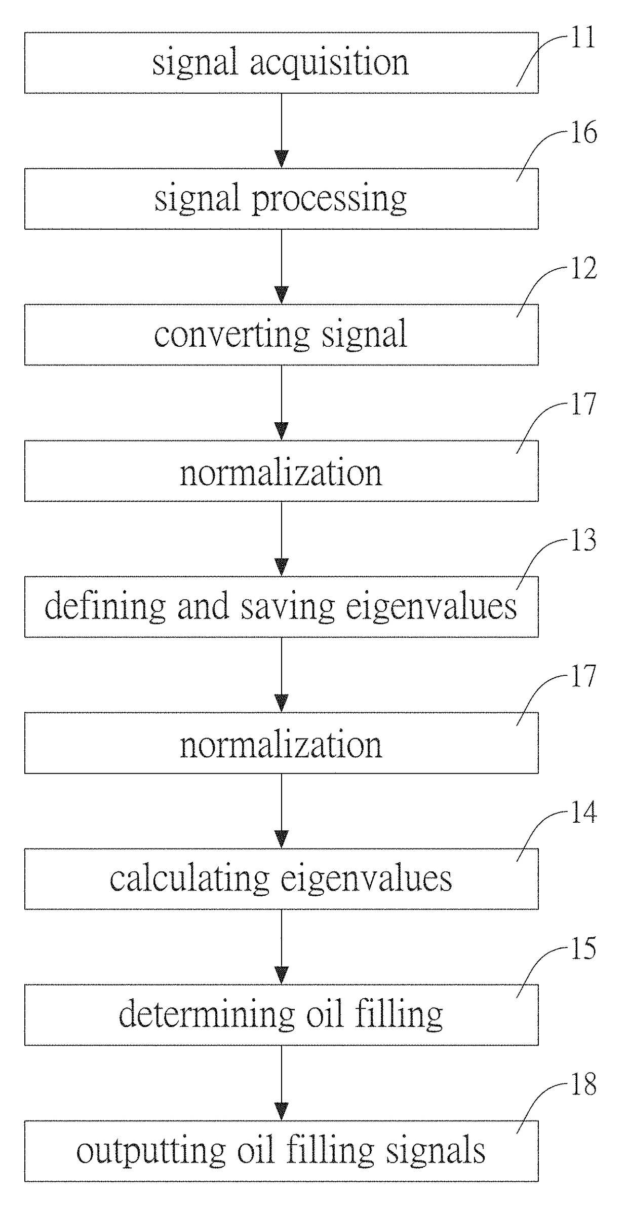
[0058]Referring to FIG. 14, a method for determining timing of oil filling for a ball screw in accordance with a fifth preferred embodiment of the present invention comprises: a step 11 of signal acquisition, a step 16 of signal processing, a step 12 of converting signal, a step 17 of normalization, a step 13 of defining and saving eigenvalues, a step 17 of normalization, a step 14 of calculating eigenvalues, a step 15 of determining oil filling, and a step 18 of outputting oil filling signals.

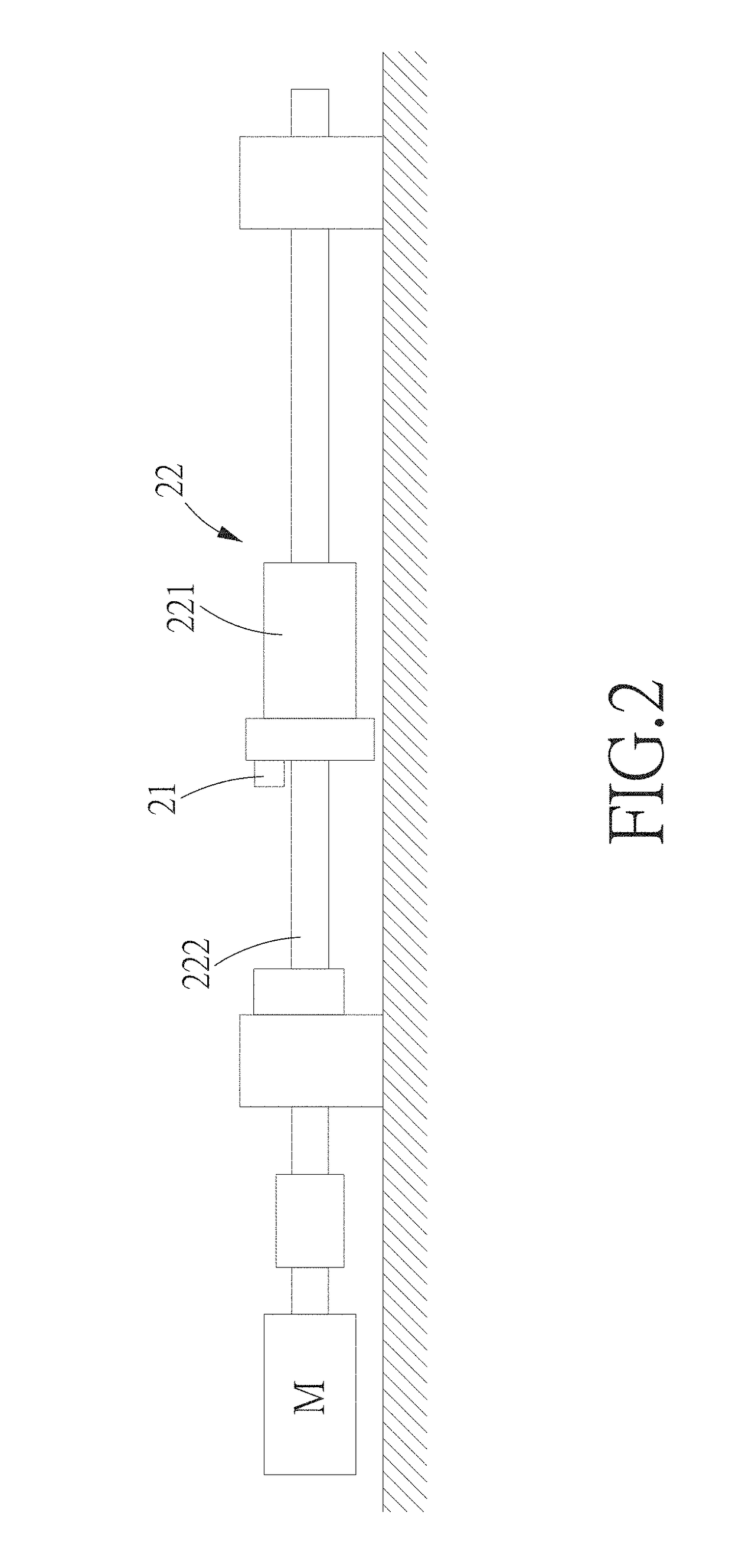
[0059]The step 11 of signal acquisition includes placing a detector 21 on the ball sc...


PUM


Abstract

A method for determining timing of oil filling for a ball screw can determine whether the oil film in a specific time period is sufficient, falling or insufficient, and then know the optimum timing of oil filling, by comparing the sum of the slope values within respective time periods with a predetermined value. The method is further capable of determining the timing of oil filling even when the rotation speed of the ball screw changes. The method includes a step of signal acquisition, a step of converting signal, a step of defining and saving eigenvalues, a step of calculating eigenvalues, and a step of determining oil filling.

Description

[0001]This application is a continuation in part of U.S. patent application Ser. No. 14 / 179,748 which claims the benefit of the earlier filing date of Feb. 13, 2014. The entire specification of which is incorporated herein by reference.BACKGROUND OF THE INVENTIONField of the Invention[0002]The present invention relates to a ball screw, and more particularly to a method for determining timing of oil filling for the ball screw.Description of the Prior Art[0003]The ball screw comprises a nut which is movably screwed on a screw via a plurality of balls. The nut can move along the screw with little friction via the balls, and the ball screw is suitable for use on various machines requiring precision motion due to its precision and low friction properties. Therefore, lubrication of the helical raceway of the ball screw is very important, otherwise, the friction between the nut and the screw would speed up the wear of the ball screw. In this case, the timing of oil filling (feeding lubrica...

Claims


Application Information

Patent Timeline
Patent Type & Authority Applications(United States)
IPC IPC(8): F16H57/04F16H57/00F16H25/22
CPCF16H57/0497F16H57/0006F16H25/2204F16H57/0405F16H57/0408F16N29/00F16N2250/18
Inventor CHU, WEI-YINGWEN, HSIAO-TINGHWANG, YIH-CHYUN
Owner HIWIN TECH
Why Eureka
Try Eureka