Eureka AIR delivers breakthrough ideas for toughest innovation challenges, trusted by R&D personnel around the world.

Devices and methods of low frequency magnetic stimulation therapy

a low frequency magnetic stimulation and low frequency technology, applied in the field of low frequency magnetic stimulation therapy, can solve the problems of serious problems for affected subjects, their families, society, and neurodegenerative disorders, and achieve the effect of increasing blood flow in the cortex of subjects

Inactive Publication Date: 2017-11-02
NEOSYNC
View PDF0 Cites 22 Cited by
  • Summary
  • Abstract
  • Description
  • Claims
  • Application Information

AI Technical Summary

Benefits of technology

The patent is about a treatment that can improve a person's cognitive function, executive function, academic performance, sports performance, peripheral visual response, attention span, immediate reaction time, movement time, simple perceptual reaction time, conflict perceptual reaction time, and any combination thereof. The treatment can also improve indicators, disorders, symptoms, dysfunctions, and characteristics of the person's brain.

Problems solved by technology

A neurological disorder generates serious problems for the affected subjects, their families, and society.

Method used


Image

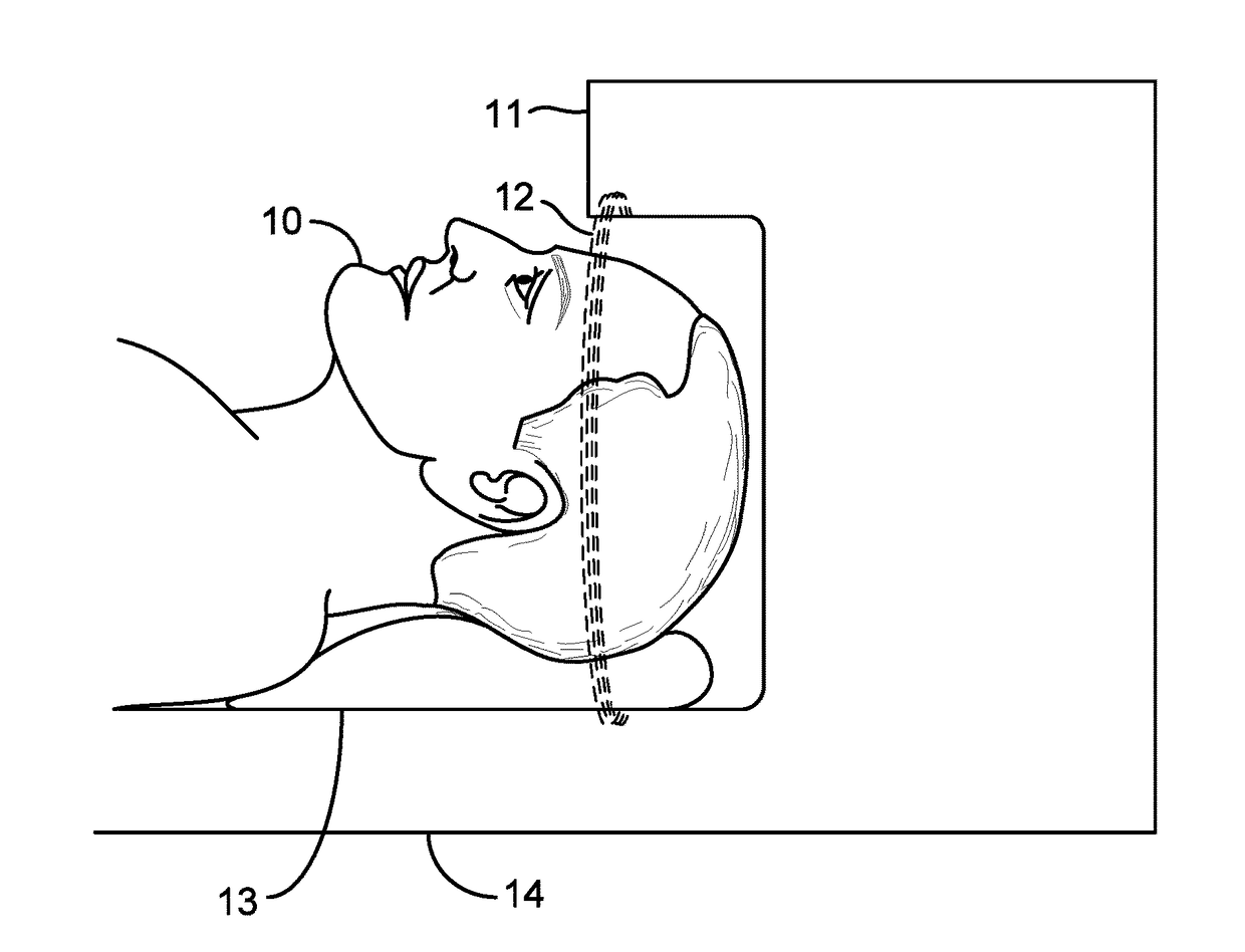
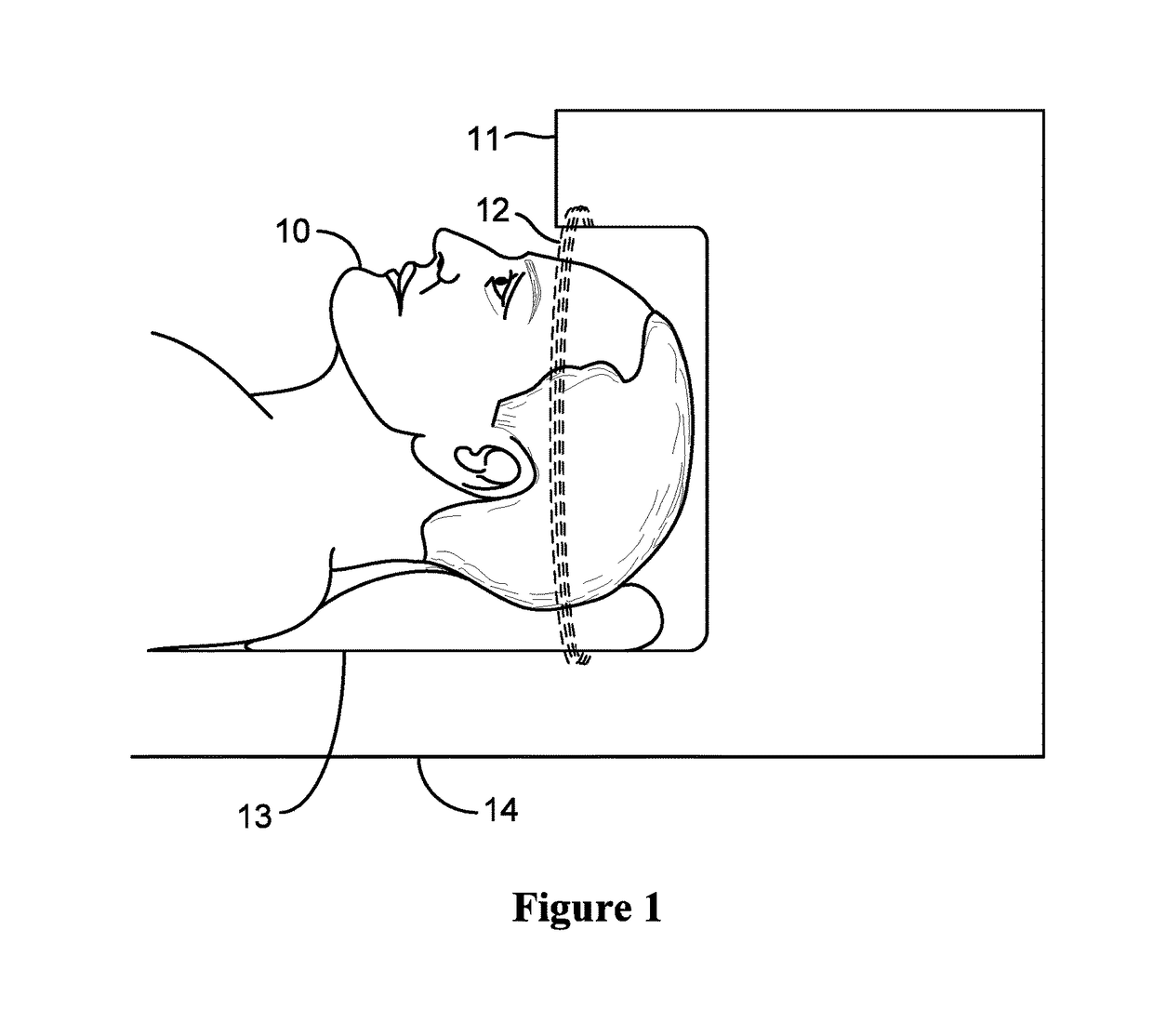
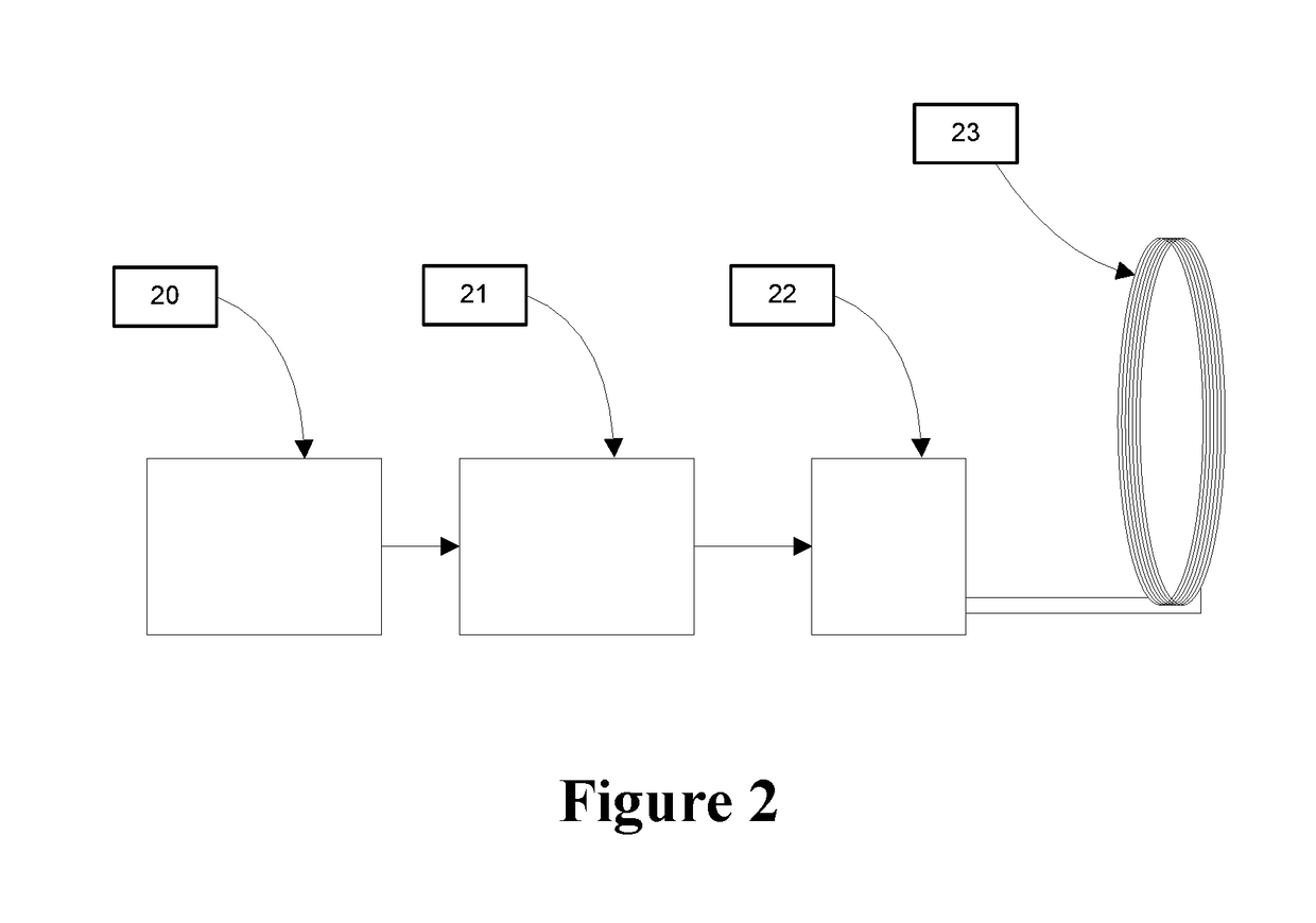
  • Devices and methods of low frequency magnetic stimulation therapy
  • Devices and methods of low frequency magnetic stimulation therapy
  • Devices and methods of low frequency magnetic stimulation therapy

Examples


example 1

ization of the Effect of Therapy on Cerebral Oscillatory Activity

[0208]In order to illustrate a possible physical model that adequately characterizes synchronization, consider the qEEG power spectrum of a subject with moderate alpha band synchrony.

[0209]FIG. 9 shows the EEG signal in the time domain (top panel) and the associated power spectrum in the frequency domain (bottom panel). The top panel is the EEG waveform. The vertical axis of the top panel is amplitude measured in mV ranging from −40 mV at the bottom to 40 mV at the top, centered at zero mV. The horizontal axis of the top panel is time measured in seconds ranging from zero at the left to 6 seconds at the right. The bottom panel is the Fourier transform of the EEG waveform depicted in the top panel. The vertical axis is the energy in the signal and ranges from zero at the bottom to two at the top. The horizontal axis is frequency measured in Hz ranging from zero at the left to 35 Hz at the right. The power spectrum shows...

example 2

l Magnetic Stimulation Synchronized to the Average IAF

[0215]In some instances, a focal pulsatile stimulation waveform over the left dorsolateral prefrontal cortex at a frequency of 10 Hz commonly is used in treatment of MDD. However, pulsed fields do not consist of a pure 10 Hz signal. An example of a pulse is shown in FIG. 13. The vertical axis is the field strength measured in Tesla ranging from −1 Tesla at the bottom to 1 Tesla at the top, centered at zero. The horizontal axis is time ranging from −0.15 seconds at the left to 0.15 seconds at the right, centered at zero. The pulse has a period of 100 milli-seconds or ten pulses per second.

[0216]FIG. 14 depicts the waveform of a single pulse of FIG. 13 on an expanded time scale. The expanded time scale shows that the pulse comprises a single sinusoidal period. In FIG. 14, the vertical axis is the field strength measured in Tesla ranging from −1 Tesla at the bottom to 1 Tesla at the top, centered at zero. The waveform has an amplitu...


PUM


Abstract

Described herein, in certain embodiments, are devices and methods for modulating the electrical activity of a brain in a targeted manner using a weak magnetic field, generally field with a strength of less than about 100 Gauss. The magnetic field is varied over time in a periodic manner, generally with a frequency tuned to specifically affect one of the intrinsic frequencies of the brain, optionally the alpha frequency. The “Low Field Magnetic Stimulation” devices and methods described herein modulate the electrical activity of a brain without requiring medication. Methods and devices described herein gently “tune” the brain and affect mood, focus, and cognition of human subjects.

Description

CROSS-REFERENCE TO RELATED APPLICATIONS[0001]This application is a continuation of U.S. patent application Ser. No. 13 / 675,466 (Phillips et al.), entitled “DEVICES AND METHODS OF LOW FREQUENCY MAGNETIC STIMULATION THERAPY” filed Nov. 13, 2012, which claims priority from U.S. Provisional Patent Application No. 61 / 559,490 (Phillips et al.), entitled “DEVICES AND METHODS OF LOW FREQUENCY MAGNETIC STIMULATION THERAPY” filed on Nov. 14, 2011, which are each incorporated herein by reference in their entireties.BACKGROUND OF THE INVENTION[0002]A neurological disorder generates serious problems for the affected subjects, their families, and society. Currently, psychiatrists and neurophysiologists treat these disorders with a variety of medications, many of which have significant negative side effects.[0003]Repetitive Transcranial Magnetic Stimulation (rTMS) uses an electromagnet placed on the scalp that generates a series of magnetic field pulses roughly the strength of an MRI scan. Some st...

Claims


Application Information

Patent Timeline
Patent Type & Authority Applications(United States)
IPC IPC(8): A61N2/02A61N2/00A61N2/06
CPCA61N2/02A61N2/06A61N2/006
Inventor PHILLIPS, JAMES W.JIN, YI
Owner NEOSYNC
Why Eureka
Eureka Blog
Learn More