
Bypass Filter Method and Device

Active Publication Date: 2017-11-02
WINCHESTER GLOBAL
View PDF1 Cites 0 Cited by
  • Summary
  • Abstract
  • Description
  • Claims
  • Application Information

AI Technical Summary

Benefits of technology

The present invention relates to a method and apparatus for retro-fitting a bypass filter system to an existing full flow oil and fuel filter system. The bypass filter system includes a retro-fittable bypass filter that directly replaces the pre-existing full flow filter. The bypass filter system filters fluid at a rate of between 0.5 and 2 litres per minute, at a pressure of between 0 and 10 psi and removes particles, moisture, oil additive package, and other impurities from the fluid. Overall, the present invention provides an efficient and effective solution for upgrading the filtration performance of an existing oil and fuel filter system.

Problems solved by technology

It is known that common spin-on oil and fuel filters used on all diesel and petrol engines result in accumulated moisture and particulate contamination.
This depletes the engine oil additive package, including Total Base Number (TBN), resulting in undesirable sludge, varnish and accelerated oil oxidation.
Also, fuel economy and emission standards prematurely deteriorate as the Original Equipment Manufacturers (OEM) design function of the fuel injection systems and piston rings become impaired.
The primary issue with common spin-on oil filters is that they are full flow (70-185 litres per minute depending on the size of the engine) at approximately 80 psi.
The technical issue with spin-on oil and fuel filters not retaining moisture in emulsion is that ‘the presence of wear metals alone can cause oxidation rates to increase to five (5) times the normal rate, while the presence of water can increase the oxidation rate ten (10) times. Combined, water and metal catalysts can increase the oxidation rate fifty (50) times or more’ (ref: USA National Tribology).
These are known to be most effective, but are mainly sold in the aftermarket, where there is consumer resistance to fitting hose connections and unwarranted concerns about engine warranty.

Method used


Image

  • Bypass Filter Method and Device
  • Bypass Filter Method and Device
  • Bypass Filter Method and Device

Examples


second embodiment

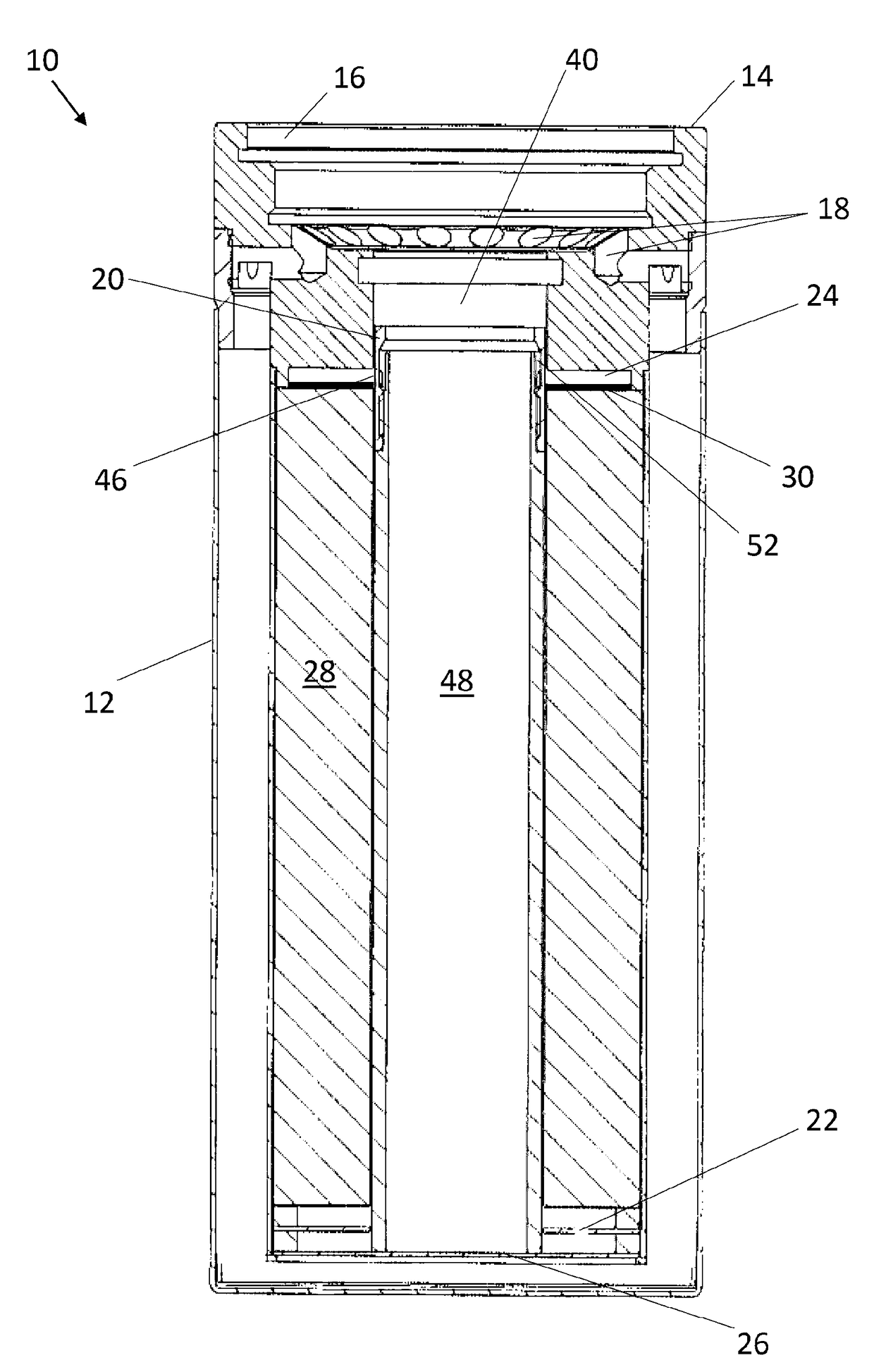
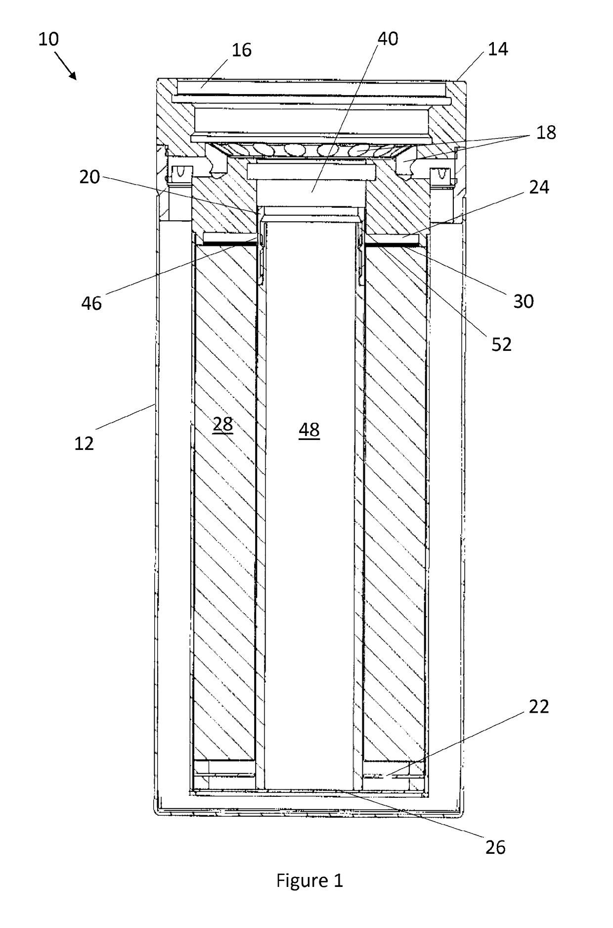
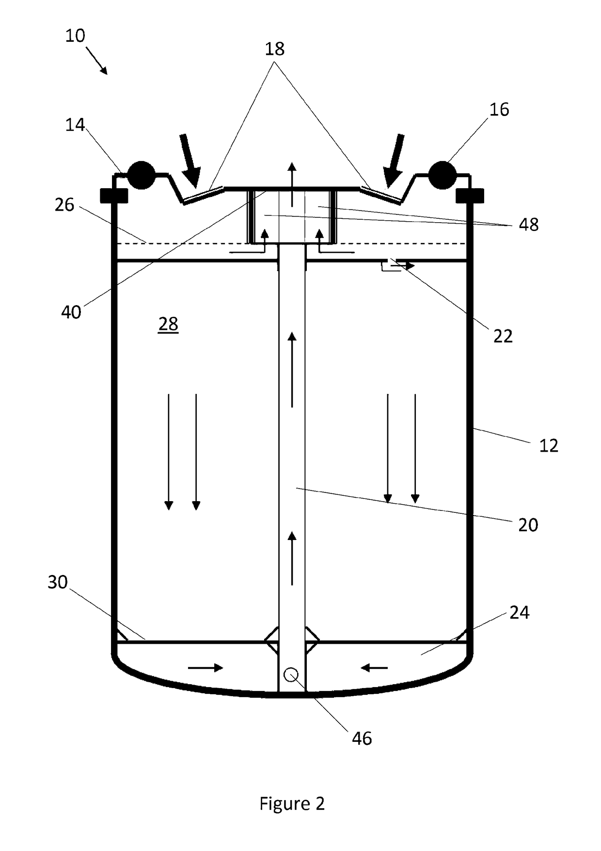
[0043]With reference to FIGS. 1 and 5, alternative embodiments of the filter 10 of the present invention are shown, with like numbers referencing like parts to the second embodiment described above. As can be seen, all fluid enters the filter 10 at the inlet ports 18 to travel to the filter screen 26, disposed distally to the inlet ports 18. Again, the fluid passes through the filter screen 26 then to either the relief channel 48 or restriction orifice 22. Accordingly, the relief channel 48 is disposed as the channel substantially centrally within, and spanning the length of, the filter 10. As with previously described embodiments, fluid which is allowed through the restriction orifice 22 and is not bypassed, passes through the cellulose filter element 28, followed by the polishing screen 30 to the cavity 24. From the cavity 24, the filtered fluid enters the supply channel 20 through the channel inlet 46 and exits the filter 10 to be provided to the engine oil gallery, for example.

third embodiment

[0044]With reference to FIG. 4, the filter 10 of the present invention is shown, with like numbers referencing like parts to the previously described embodiments. Again, fluid enters the filter through the inlet ports 18 and passes through the filter screen 26. The majority of fluid then enters the relief channel 48 and exits the filter 10 though the relief outlet 40 and is subsequently “bypassed”. The minor volume of fluid allowed through the restriction orifice 22 is further filtered through firstly the cellulose filter element 28, then through the polishing screen 30. This “filtered” fluid then enters the supply channel 20 to exit the filter 10.

[0045]The relief channel 48 of the filter 10 provides a fluid connection between the inlet port 18 and a relief outlet 40 through which fluid which entered the inlet port 18 and relief channel 48 may return to the oil reservoir. It is preferred that the filter 10 comprises a venturi effect 52, between the supply channel 20 and the relief c...


PUM

PropertyMeasurementUnit
Fractionaaaaaaaaaa
Pressureaaaaaaaaaa
Pressureaaaaaaaaaa

Abstract

The present invention relates to a method for converting a full flow oil and / or fuel filter system into a bypass filter system comprising the use of a retro-fittable bypass filter configured to directly replace the pre-existing full flow filter, without the need for additional hoses or mounts etc. as in existing methods. Also described is a filter device for converting a full flow oil and / or fuel filter system into a bypass filter system comprising: an inlet for allowing fluid into the filter; a plurality of screens for filtering particles from the fluid; a cellulose element for filtering moisture from the fluid; an outlet for allowing fluid out of the filter; and a bypass for fluid to bypass the cellulose element and at least one screen and exit the filter, wherein the bypass filter is configured to directly replace the pre-existing full flow filter.

Description

FIELD OF THE INVENTION[0001]The present invention relates to a bypass filter method and device.BACKGROUND[0002]It is known that common spin-on oil and fuel filters used on all diesel and petrol engines result in accumulated moisture and particulate contamination. This depletes the engine oil additive package, including Total Base Number (TBN), resulting in undesirable sludge, varnish and accelerated oil oxidation. Also, fuel economy and emission standards prematurely deteriorate as the Original Equipment Manufacturers (OEM) design function of the fuel injection systems and piston rings become impaired. Hence, the engine oil is ‘spent’ at only 250-500 hours in a diesel engine and 10,000 miles in a car petrol engine.[0003]The primary issue with common spin-on oil filters is that they are full flow (70-185 litres per minute depending on the size of the engine) at approximately 80 psi. They only start filtering particulate at 30 to 40 μm and have no capacity to absorb or retain moisture...

Claims


Application Information

Patent Timeline
IPC IPC(8): B01D35/147F02M37/22B01D15/00B01D36/00B01D29/58F01M11/03F02M37/34F02M37/42
CPCB01D35/147B01D36/003B01D29/58F01M2011/031F01M11/03F02M37/22B01D2201/208B01D15/00B01D27/146B01D35/306B01D37/025B01D27/07B01D27/103F01M2001/1092F02M37/42F02M37/34
Inventor RYNBEEK, COLIN JAMES
Owner WINCHESTER GLOBAL
Learn More