Fuel supply device

a fuel supply device and fuel supply technology, applied in the direction of fuel injection apparatus, machine/engine, charge feed system, etc., can solve the problems of direct impact of the pump unit, may possibly fail to operate properly, and vibration of the fuel tank holding the sub-tank and the further components of the vehicle, so as to increase the reliability of the fuel pumping function and reduce the effect of noise generation

Inactive Publication Date: 2017-11-02
DENSO CORP +1
View PDF7 Cites 15 Cited by
  • Summary
  • Abstract
  • Description
  • Claims
  • Application Information

AI Technical Summary

Benefits of technology

[0007]The present disclosure has an object to provide a fuel supply device restricting an occurrence of a failure and generation of noise.
[0008]According to a first aspect of the present disclosure, the fuel supply device which supplies a fuel in a fuel tank to an internal combustion engine outside the fuel tank in a vehicle includes a sub-tank held inside the fuel tank, a pump unit housed in the sub-tank and discharging the fuel stored in the sub-tank to the internal combustion engine by pressurizing the fuel, a jet pump installed on a bottom of the sub-tank to pump the fuel stored in the fuel tank into the sub-tank by jetting a pressurized fuel guided from the pump unit, and a connection structure connected with the pump unit and the jet pump. The connection structure has a guide part that is a cylindrical shape, is provided to the pump unit, and guides the pressurized fuel toward the bottom in an axial direction, a pressurizing part that is a cylindrical shape, is provided to the jet pump, and is fitted to the guide part from a side of the bottom in an axially slidable manner, to which the pressurized fuel is guided from the guide part, a shock-absorbing member that has a low spring constant that is predetermined and mitigates an axial impact between the guide part and the pressurizing part, and a sealing member that has a high spring constant higher than the low spring constant of the shock-absorbing member and radially seals a space between the guide part and the pressurizing part.
[0009]In the connection structure connected with the pump unit and the jet pump in the fuel supply device, the pressurizing part of the jet pump is fitted to the guide part of the pump unit in an axially slidable manner from the side of the bottom of the sub-tank. Owing to such a fitting configuration of the guide part and the pressurizing part, the shock-absorbing member having the low spring constant mitigates an axial impact between the guide part and the pressurizing part. Hence, even when an impact of relatively large amplitude is made to the jet pump installed on the bottom of the sub-tank while the vehicle is moving, the impact which has propagated from the side of the bottom of the sub-tank to the pressurizing part can be mitigated by the shock-absorbing member having the low spring constant. Consequently, because the pump unit hardly receives an external impact directly, an occurrence of a failure can be restricted.
[0010]According to the fuel supply device, owing to the fitting configuration of the guide part and the pressurizing part as above, the sealing member having the high spring constant higher than the low spring constant of the shock-absorbing member radially seals a space between the guide part and the pressurizing part. Accordingly, by using the sealing member having the high spring constant and capable of limiting fuel leakage in a guide path from the guide part toward the pressurizing part, vibrations of relatively small amplitude generated in association with a fuel supplying operation of the pump unit can be attenuated between the guide part and the pressurizing part. Hence, because vibrations from the pump unit hardly propagate directly to the jet pump installed on the bottom of the sub-tank, generation of noise due to vibrations of the fuel tank holding the sub-tank and further vibrations of components forming the vehicle can be restricted.
[0012]According to the first embodiment, the pressurizing part is inserted in the guide part on the inner peripheral side and the sealing member between the pressurizing part and the guide part is stopped by the shoulder surface of the pressurizing part from the side of the bottom of the sub-tank in the axial direction. The sealing member between the guide part and the pressurizing part is thus capable of exerting not only the sealing function but also a vibration attenuation function in a stable manner. Consequently, reliability of a noise generation restricting effect can be increased. Moreover, because the sealing member exerts the sealing function on pressurized fuel which has entered the space between the guide part and the pressurizing part on the inner peripheral side of the guide part, the shoulder surface is pressed against the bottom of the sub-tank by the pressurized fuel via the sealing member. Consequently, because the jet pump can be positioned while being pressed against the bottom of the sub-tank, reliability of a fuel pumping function can be increased.

Problems solved by technology

In the fuel supply device disclosed in Patent Literature 1, however, the pump unit and the jet pump are fixed so tightly that when an impact of relatively large amplitude is made to the jet pump installed on the bottom of the sub-tank while a vehicle is moving, the pump unit directly receives the impact and may possibly fail to operate properly.
In addition, when vibrations of relatively small amplitude generated in association with a fuel supply operation of the pump unit propagate directly to the jet pump installed on the bottom of the sub-tank, the fuel tank holding the sub-tank and further components forming the vehicle may vibrate and generate noise.
Consequently, because the pump unit hardly receives an external impact directly, an occurrence of a failure can be restricted.

Method used


Image

  • Fuel supply device
  • Fuel supply device
  • Fuel supply device

Examples


first embodiment

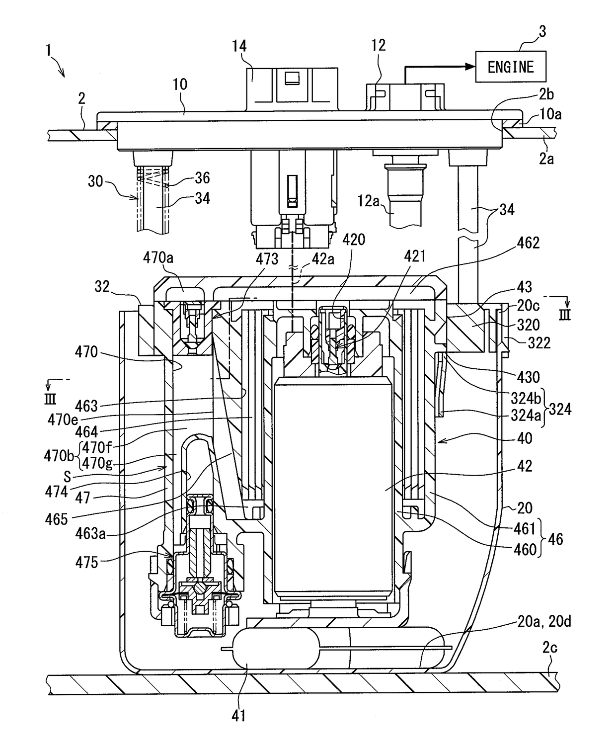
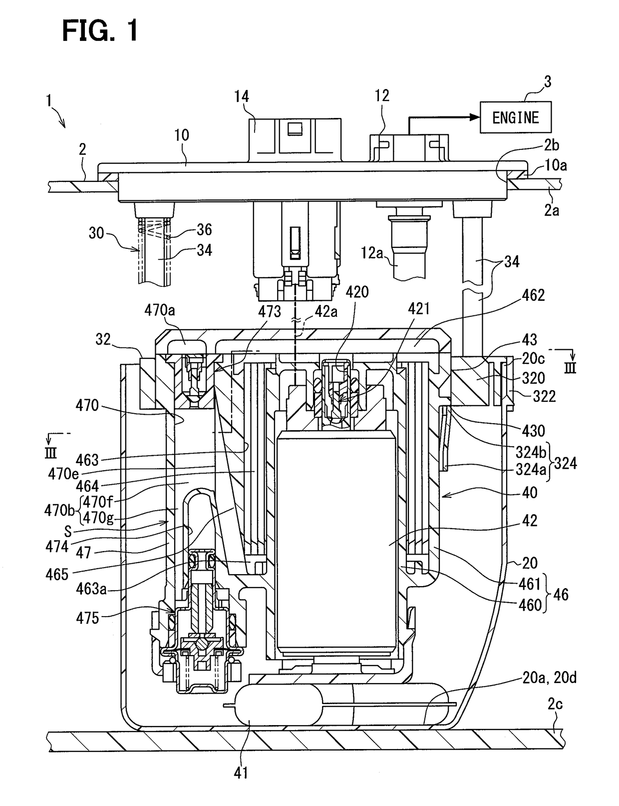
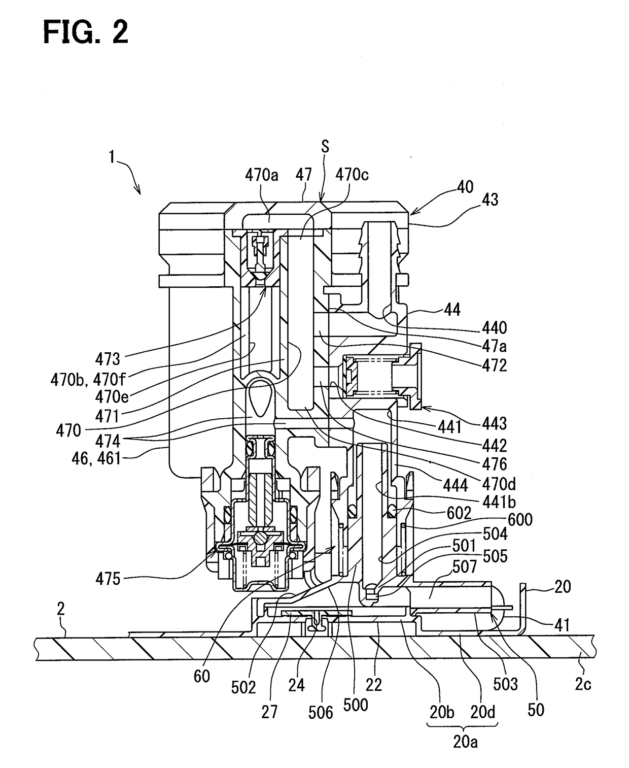
[0028]As are shown in FIGS. 1 and 2, a fuel supply device 1 according to a first embodiment of the present disclosure is installed to a fuel tank 2 in a vehicle. The fuel supply device 1 supplies fuel in the fuel tank 2 to fuel injection valves of an internal combustion engine 3 either directly or indirectly via a high-pressure pump or the like. The fuel tank 2, to which the fuel supply device 1 is installed, is made of resin or metal and formed in a hollow shape to store fuel to be supplied to the internal combustion engine 3. The internal combustion engine 3 supplied with fuel from the fuel supply device 1 may be a gasoline engine or a diesel engine. A top-bottom direction of the fuel supply device 1 shown in FIGS. 1 and 2 substantially coincides with a top-bottom direction of the vehicle on a level plane.

[0029]Hereinafter, a configuration and an operation of the fuel supply device 1 will be described.

[0030]As are shown in FIGS. 1 to 4, the fuel supply device 1 includes a flange 1...


PUM


Abstract

A fuel supply device includes a sub-tank, a pump unit, a jet pump, and a connection structure connected with the pump unit and the jet pump. The connection structure has a guide part that is provided to the pump unit and guides the pressurized fuel toward the bottom in an axial direction, a pressurizing part that is provided to the jet pump and is fitted to the guide part from a side of the bottom in an axially slidable manner, to which the pressurized fuel is guided from the guide part, a shock-absorbing member that has a low spring constant that is predetermined and mitigates an axial impact between the guide part and the pressurizing part, and a sealing member that has a high spring constant higher than the low spring constant of the shock-absorbing member and radially seals a space between the guide part and the pressurizing part.

Description

CROSS REFERENCE TO RELATED APPLICATION[0001]This application is based on Japanese Patent Application No. 2014-226226 filed on Nov. 6, 2014, the disclosure of which is incorporated herein by reference.TECHNICAL FIELD[0002]The present disclosure relates to a fuel supply device which supplies fuel in a fuel tank to an internal combustion engine outside the fuel tank in a vehicle.BACKGROUND ART[0003]A fuel supply device in the related art has a pump unit which is housed in a sub-tank held inside a fuel tank and the pump unit pressurizes fuel stored in the sub-tank and discharges pressurized fuel to an internal combustion engine.[0004]Patent Literature 1 discloses a type of the fuel supply device as above, in which a jet pump is installed on a bottom of a sub-tank to pump fuel stored in a fuel tank into the sub-tank by jetting pressurized fuel guided from a pump unit.PRIOR ART LITERATURESPatent Literature[0005]Patent Literature 1: U.S. Pat. No. 7,765,990SUMMARY OF INVENTION[0006]In the f...

Claims


Application Information

Patent Timeline
Patent Type & Authority Applications(United States)
IPC IPC(8): F02M37/10F02M55/04
CPCF02M55/04F02M37/106F02M37/0029F02M37/025F02M37/103
Inventor TAKAHASHI, HIDETOOOHASHI, MASAHARUOKAZONO, TETSUROOKI, HIRONOBU
Owner DENSO CORP
Why Eureka
Try Eureka