Force Mitigating Athletic Shoe

a technology of athletic shoes and force, applied in the field of athletic shoes, can solve the problems of reducing the traction of the shoe/playing surface, reducing preventing non-compliance, so as to prevent the generation of injurious force, and reduce the risk of injury

Active Publication Date: 2017-11-09
RASMUSSEN JEFFREY MARK +2
View PDF5 Cites 13 Cited by
  • Summary
  • Abstract
  • Description
  • Claims
  • Application Information

AI Technical Summary

Benefits of technology

[0007]The present invention involves three embodiments of an athletic shoe designed to provide a mitigating deformation induced by a particular athlete's pre-determined, target, pre-injury force threshold and a method of preventing injury to an athlete's lower extremity joints. As different athletes, according to mass, speed, strength, playing surface conditions, etc. generate a wide range of forces, a wide range of force thresholds must be contemplated. Each embodiment of the invention permits an athletic shoe sole to be designed and constructed to permit a mitigating deformation induced by a particular athlete's pre-determined, target, pre-injury force threshold. This construction method allows a fine-tuning of the force threshold, allowing an individual athlete to have a shoe built to protect him or her from injurious forces.
[0022]Use of 3-D printing construction method allows fine-tuning of the composite sole to construct a sole that can prevent the generation of injurious force to an athlete's lower extremities.

Problems solved by technology

At some point, the human body is naturally unable to compensate for this force.
Yet few attempts at preventing non-contact ACL injuries have involved a viable athletic-shoe solution.
Results have yielded shoe designs with unstable vertical profiles that compromise athletic performance and increase injury risk.
In spite of these, the incidence of non-contact ACL injuries continues to rise—painful proof that a practical solution has yet to be realized.

Method used


Image

  • Force Mitigating Athletic Shoe
  • Force Mitigating Athletic Shoe
  • Force Mitigating Athletic Shoe

Examples


first embodiment

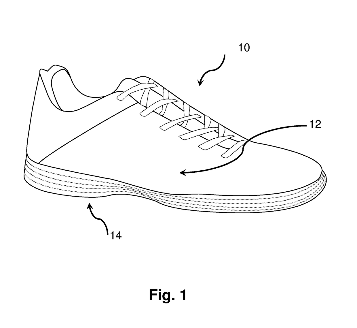
[0046]The athletic shoe 10 according to the invention is shown in FIGS. 1-8. The athletic shoe soles shown in FIGS. 1-8 are designed to protect an athlete's lower extremities against both injurious torsional [torque] forces and injurious longitudinal forces.

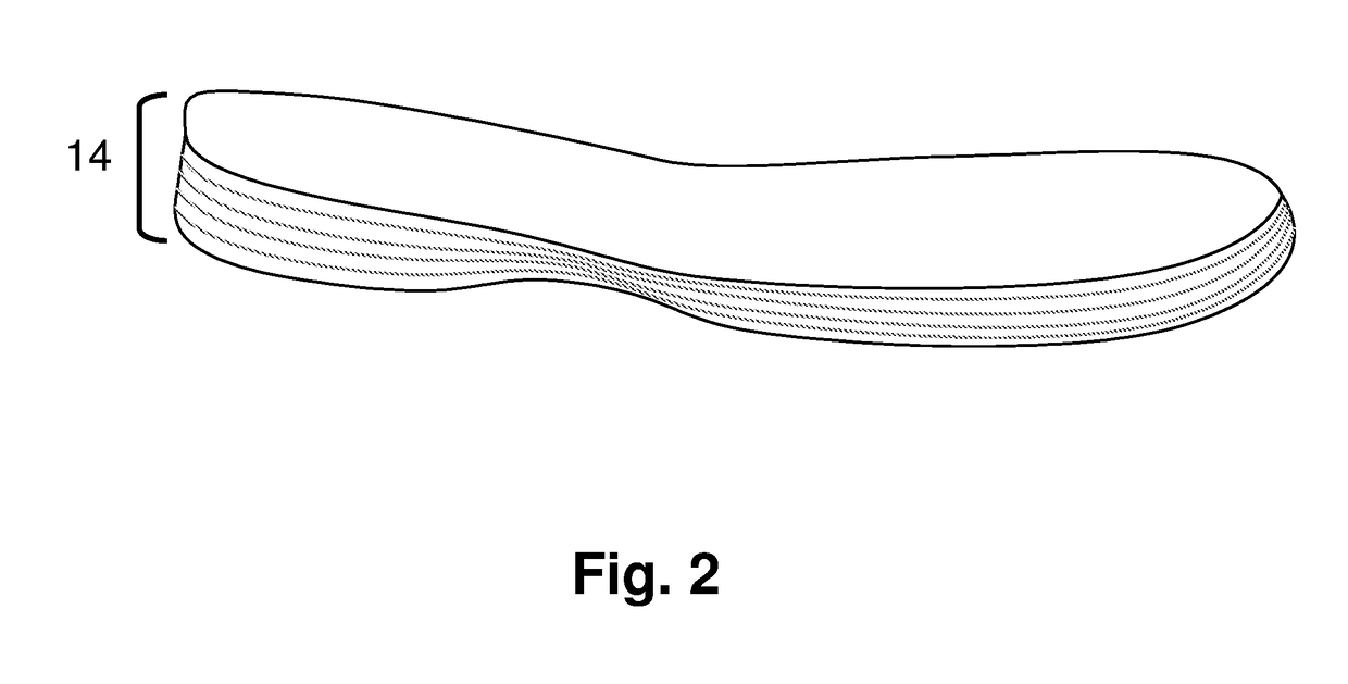
[0047]The shoe sole shown in FIGS. 1-8 comprises an upper body 12 and a multi-layer composite sole 14. Multi-layer composite sole 14 is shown in FIGS. 2-8 as comprising 5 thin layers of materials, although the exact number of layers could be more or less than 5 depending upon the specific situation the shoe is designed for. As shown in FIG. 3, sole 14 comprises layers 20, 21, 22, 23 and 24. Layers 20, and 24 are designed to provide rigid translational (straight ahead) stability during competition, like a traditional athletic shoe, only up to a pre-determined, athlete-specific, pre-injury target force threshold. These layers will also contribute limited rigidity during lateral as well as rotational (twisting) force generation. Lay...

second embodiment

[0056]FIGS. 12-14 show an athletic shoe sole constructed according to the invention. The three figures will be described together with it being understood that elements shown in one figure may or may not be shown in the other figures.

[0057]Sole 70 is a multi-layer composite sole similar in construction to the first embodiment soles shown and described above. Multi-layer composite sole 70 is shown as comprising composite layers 73, 74, and 75, although the exact number of layers could be more or less, as desired. Sole 70 comprises materials similar to those of the first embodiment. Multi-layer sole 70 has a cut-out or channel 72 incised into the outer surface of layer 73. Channel 72 is shown in the figures as being incised into the forward portion of sole 70. It should be understood that the exact placement of channel 72 can and will vary depending upon the desired force-resisting characteristics of sole 70 just as the width, depth and exact pathway of channel 72 can and will be vari...

third embodiment

[0061]FIGS. 16-23 show the invention. In this embodiment the sole is strategically weakened to provide the desired temporary deformation via inserts in the sole rather than by incising a channel in the sole. FIGS. 16 and 17 will be described together with it being understood that elements shown in one figure may or may not be shown in the other figure. It is noted that the inserts are all shown in the forward [toe] portion of the sole. Obviously, one or more inserts could be positioned in the mid portion of the sole, or even in the heel portion of the sole, if desired.

[0062]Sole 110 is a multi-layer composite sole similar in construction to the first and second embodiment soles shown and described above. The forward portion of sole 110 contains 4 inserts, 112, 112′, 114 and 114′. These inserts are made of a composite filler material similar to the sole materials described above; however, the filler material may or may not include bound fibers. The filler material of the inserts will...


PUM

PropertyMeasurementUnit
pre-injury force thresholdaaaaaaaaaa
force thresholdaaaaaaaaaa
stabilityaaaaaaaaaa

Abstract

Each year in North America there are approximately 175,000 non-contact ACL injuries. One of the main causes of these injuries is the rotational and translational forces created when a player makes a sudden change in direction or stops. Every athlete subjects their lower extremities to various forces that are unique to his or her mass, speed, and strength. These forces are affected by composition of the playing field surface, shoe sole design and construction, and other factors. Using these and other factors, the level of force at which injury is inevitable (pre-injury force) is determined and an athletic shoe is created which will provide a mitigating deformation induced by a particular athlete's pre-determined, pre-injury force threshold. A mitigating deformation of as little as 2 degrees can significantly reduce injurious forces. After the athlete has progressed through that particular force-generating movement, the shoe's sole instantly returns to its original shape.

Description

CROSS-REFERENCE TO RELATED APPLICATIONS[0001]This application claims the benefit of and incorporates by reference U.S. patent application 62 / 156,276 filed on 3 May 2015.STATEMENT REGARDING FEDERALLY SPONSORED RESEARCH OR DEVELOPMENT[0002]Not ApplicableSEQUENCE LISTING[0003]Not ApplicableBACKGROUND OF THE INVENTION[0004]Each year in North America there are approximately 250,000 ACL injuries—about 70% of which are non-contact incidents. [Griffin LY. Noncontact Anterior Cruciate Ligament Injuries: Risk Factors and Prevention Strategies. [Journal of the American Academy of Orthopaedic Surgeons: 2000; 8:141-150] A near universally accepted and scientifically supported explanation for this non-contact statistic is the rotational and translational forces created when a player makes a sudden change in direction or stops. Exacerbating this natural force generation is athletic-shoe / playing-surface interfacetraction. Decades of private and academic studies prove a causal relationship between t...

Claims


Application Information

Patent Timeline
Patent Type & Authority Applications(United States)
IPC IPC(8): A43B13/18A43B13/12A43B13/04A43B13/02A43B13/42A43B5/00
CPCA43B13/187A43B13/026A43B13/04A43B5/00A43B13/181A43B13/42A43B13/12A43B13/023A43B13/141A43B13/188B33Y80/00
Inventor RASMUSSEN, JEFFREY MARKRASMUSSEN, JACK STEARNS
Owner RASMUSSEN JEFFREY MARK
Why Eureka
Try Eureka