Rotor or propeller blade with dynamically variable geometry and other properties

a technology of rotating or propeller blades and dynamically variable geometry, which is applied in the direction of rotary propellers, machines/engines, transportation and packaging, etc., to achieve the effect of better control of hydro-elastic or aeroro-elastic effects

Active Publication Date: 2017-11-09
OPTIVECTOR LTD
View PDF1 Cites 9 Cited by
  • Summary
  • Abstract
  • Description
  • Claims
  • Application Information

AI Technical Summary

Benefits of technology

[0004]One object is to provide the blades for the cycloidal propellers and the cycloidal rotors of any kind, with the means for blade based powered flexing of blades cross-sectional shape dynamically.
[0005]Another object is to provide the blades for the above referenced propellers and rotors with the capability of dynamically changing their physical pivot point location along the blade chord for controlling the relative sizes of the leading and trailing edge vortexes.
[0006]Another object is to provide the blades for said propellers and rotors with the ability to dynamically change the blade's planform by means of extending or retracting a trailing edge extension, which may be extended differentially at the two ends of the blade depending on the current aerodynamic or hydrodynamic regime respectively at each end, for controlling the size, shape along the span, movement along the span, generation and sheddin

Problems solved by technology

The ability to switch between the rigid and flexible status of the leading and trailing edges when the roles of said leading and trailing edges are reversed for operation in the regime of reverse airflow and in other cases is h

Method used


Image

  • Rotor or propeller blade with dynamically variable geometry and other properties
  • Rotor or propeller blade with dynamically variable geometry and other properties
  • Rotor or propeller blade with dynamically variable geometry and other properties

Examples


first embodiment

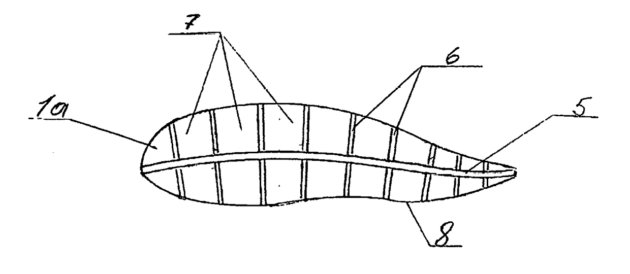
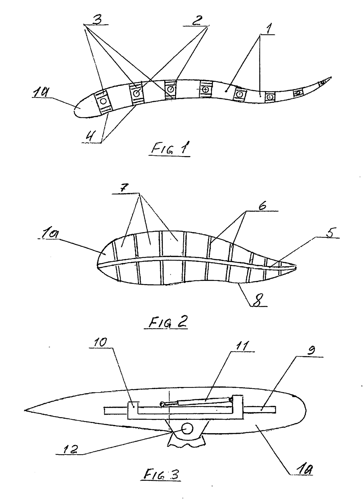
[0021 of this invention (FIG. 1) is a blade (1a) comprising a number of parallel segments (1) which are connected either by hinges (2) or by flexible links thereby forming a cross-sectionally flexible surface. Possible configurations of this blade may comprise segments of unequal dimensions along the chord with, for example the first segment starting from the leading edge being the longest. Said segments will have plates to which will be attached, spanning the gap between said segments, miniature where appropriate, actuators (3) such as for example very fast acting electro-active polymer actuators, piezo-electric crystal stack actuators or the amplified piezo-electric actuators for the airfoil blades and for much slower moving hydrofoil blades for example the electro-magnetic actuators, electro-active polymer actuators or the smart memory alloy-based actuators. Over the gap the elastic flaps (4), extending from one segment to the segment following it, can be provided. Said flap can ...

second embodiment

[0022 will comprise a blade either of a fixed cross-sectional shape or of variable shape (FIG. 3) mounted on both ends onto the support plates (9) which are slidably mounted onto a short pivoted tracks (10). On said pivoted (12) track are attached the corresponding ends of the suitable actuators (11) while the opposing ends of said actuators are attached to the carriages. The suitable fast acting actuators can be for example the electro-active polymer based or the piezo-electric with amplification actuators. It is possible that the carriages are mounted inside another pair of carriages with the actuators attached to the inner and outer carriages in the same manner as described above for the support plates (9) and a pivoted short track (10). The purpose of that is to have the carriages with actuators moving in a staggered manner to increase the distance of blade movement relative to the pivot point, because the actuators that are required for the airfoils with real time pivot point r...

third embodiment

[0023 of the blade of this invention (FIG. 4) will comprise a blade either of a fixed shape or a flexible blade as described in the first embodiment. On the suitable elements of the blade structure there will be mounted 2 fast acting linear actuators (13) which are in turnable attachment to pins (14). On the left the pin (14) is mounted on movable support (15). Said support is movable along the short track (16) to accommodate the differential moves of the left and right sides of the trailing extension (17). There can be many other different design solutions for the simple task of extending and retracting the trailing extension which would still be within the scope and the spirit of this invention. The extension or retraction of said trailing extension will result in redistribution of its mass forward or backward which can be neutralized by the use of counterbalancing of such movements similar to what has been described in U.S. Pat. No. 8,540,485 and / or the patent application PCT / IL2...


PUM


Abstract

A blade is provided for the cycloidal marine propellers or cycloidal aerial rotors. Said blade is provided with the capabilities, in response to the control system commands to dynamically and in real time; flex itself along its chord in any required way, vary its relative pivot point position, change its planform by extending or retracting a trailing edge extension, differentially if needed on the right and left, turn the flap along the trailing edge in either direction or allow it to be turned by the flows. Said blade is also optionally provided with one or more elastic trailing edges whose stiffness is dynamically, and possibly differentially along the blade span, variable by the control system. For the reversal of the leading and trailing edges for operation in reverse airflow and other conditions the blades are provided with edges that can be made rigid when functioning as the leading edge and flexible if needed when functioning as the trailing edge. Also the blades are provided with the capability of varying their cross-sectional profile thickness and reshaping it. Finally the blades are given on command flow permeability along much of their surface. These capabilities will enable each control system controlled blade to continually optimally adjust to and make the best use of its immediate operating environment as it travels along its trajectory within each revolution.

Description

[0001]This application claims the benefit of Provisional Patent Application 62 / 159,231 filed on May 9, 20151. FIELD OF THE INVENTION[0002]This invention relates to blades for the cycloidal propellers and rotors and especially to the blades for the non-circular orbiting cycloidal rotors and propellers.2. DESCRIPTION OF THE PRIOR ART[0003]At the present time the known blades for the orbiting cycloidal propellers and rotors, such as for example described in the U.S. Pat. No. 8,540,485, are of fixed cross-sectional shape. However the patent application PCT / IL2013 / 050755 for a rotor or propeller featuring the independent from the other blades in terms of the trajectory and in terms of speed, largely unconstrained by the rotor structure blades' motion (hereinafter free blade motion) does also describe the blades designed to be cross-sectionally flexible by means of being provided either with the hinges running along the length of the blade span or making the blades cross-sectionally flexi...

Claims


Application Information

Patent Timeline
IPC IPC(8): B64C11/18B64C11/00B63H1/26
CPCB64C11/18B63H1/26B64C11/003B64C11/20B63H1/04B63H1/08F05B2240/31Y02E10/72F03D1/0675
Inventor BOGRASH, PHILIP
Owner OPTIVECTOR LTD
Why Eureka
Try Eureka