Feeder duct assembly with flexible end fittings

a flexible end fitting and feeder duct technology, applied in the direction of machines/engines, efficient propulsion technologies, stators, etc., can solve the problems of system weight and system dynamic performance compromis

Active Publication Date: 2017-11-09
UNISON INDUSTRIES
View PDF5 Cites 3 Cited by
  • Summary
  • Abstract
  • Description
  • Claims
  • Application Information

AI Technical Summary

Problems solved by technology

Current systems use ball joints or axial joints in the duct to meet requirements for flexi

Method used


Image

  • Feeder duct assembly with flexible end fittings
  • Feeder duct assembly with flexible end fittings
  • Feeder duct assembly with flexible end fittings

Examples


Embodiment Construction

[0012]The described embodiments of the present innovation are directed to systems, methods, and other devices related to routing air flow in a turbine engine. For purposes of illustration, the present innovation will be described with respect to an aircraft gas turbine engine. It will be understood, however, that the innovation is not so limited and may have general applicability in non-aircraft applications, such as other mobile applications and non-mobile industrial, commercial, and residential applications.

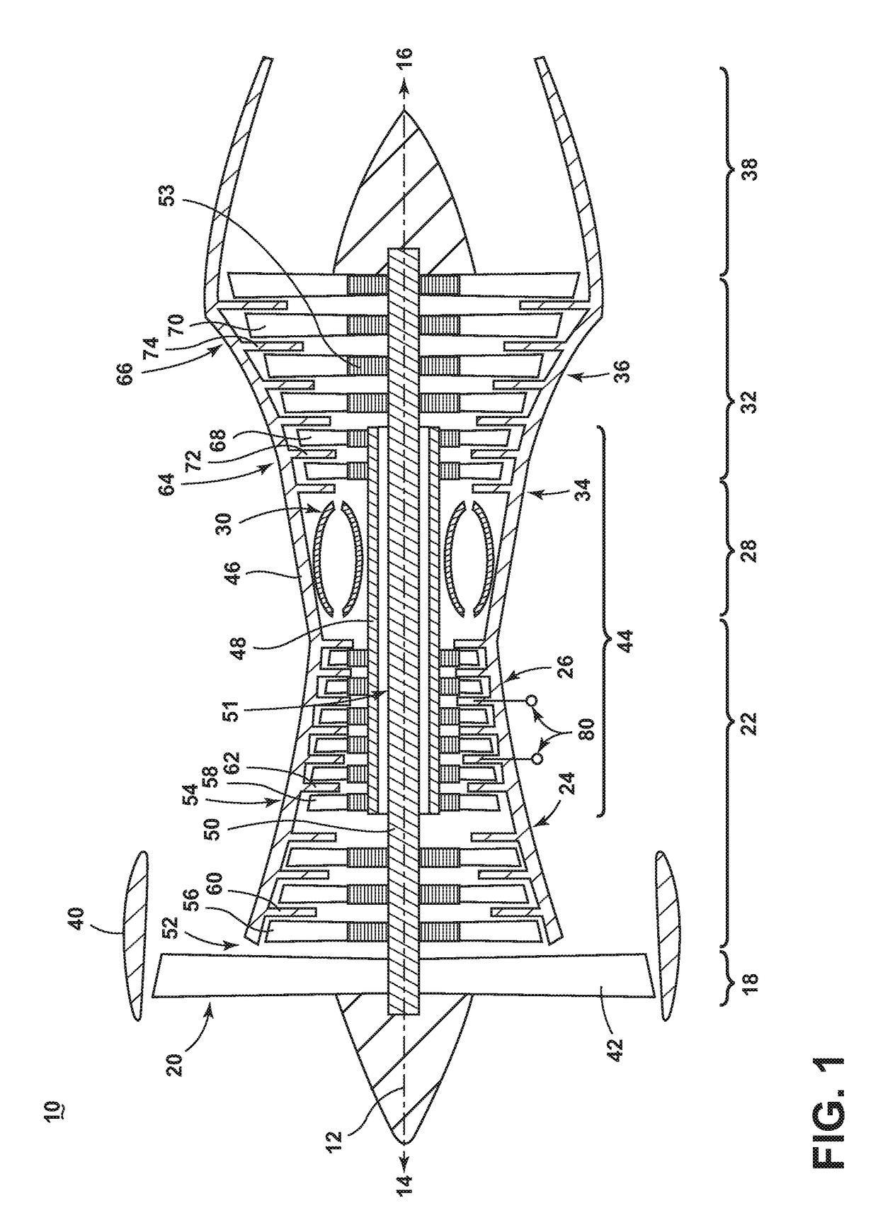
[0013]FIG. 1 is a schematic cross-sectional diagram of a gas turbine engine 10 for an aircraft. The engine 10 has a generally longitudinally extending axis or centerline 12 extending from forward 14 to aft 16. The engine 10 includes, in downstream serial flow relationship, a fan section 18 including a fan 20, a compressor section 22 including a booster or low pressure (LP) compressor 24 and a high pressure (HP) compressor 26, a combustion section 28 including a combustor 30, a ...


PUM


Abstract

A feeder duct assembly for a gas turbine engine, which negates the need for a ball or axial joint in the duct for required for flexibility under thermal loading. The feeder duct assembly of the present innovation comprises an end fitting designed to meet flexibility requirements without compromising dynamic performance of the system with added weight from ball or axial joints in the ducts.

Description

BACKGROUND OF THE INVENTION[0001]Turbine engines, and particularly gas or combustion turbine engines, are rotary engines that extract energy from a flow of combusted gases passing through the engine in a series of compressor stages, which include pairs of rotating blades and stationary vanes, through a combustor, and then onto a multitude of turbine stages, also including multiple pairs of rotating blades and stationary vanes.[0002]Feeder duct assemblies are provided about the turbine engine and provide conduits for the flow of various operating fluids to and from the turbine engine. One of the operating fluids is bleed air. In the compressor stages, bleed air is produced and taken from the compressor via feeder ducts. Bleed air from the compressor stages in the gas turbine engine can be utilized in various ways. For example, bleed air can provide pressure for the aircraft cabin, keep critical parts of the aircraft ice-free, or can be used to start remaining engines. Configuration o...

Claims


Application Information

Patent Timeline
IPC IPC(8): F01D9/02F01D11/00
CPCF01D9/023F05D2260/31F01D11/003B64D33/00F02C6/08F02C7/28F02C9/18F05D2260/30Y02T50/60F16L23/18F16L23/02F16L27/12F16L23/12F16L23/14
Inventor JONNALAGADDA, DATTU G VJANKIN, GREEDARAN KUBENDRANGRAHAM, BRUCE PATRICKSIVAPRASAD, RACHAMADUGUMILLWARD, DOUGLAS
Owner UNISON INDUSTRIES
Why Eureka
Try Eureka