Power ramp rate limiter for wind turbines

Inactive Publication Date: 2017-11-16
VESTAS WIND SYST AS
View PDF2 Cites 5 Cited by
  • Summary
  • Abstract
  • Description
  • Claims
  • Application Information

AI Technical Summary

Benefits of technology

[0005]It is an object of the invention to improve the control of a wind turbine in relation to handling power ramping requireme

Problems solved by technology

Power ramping requirements originating from grid codes may be in con

Method used


Image

  • Power ramp rate limiter for wind turbines
  • Power ramp rate limiter for wind turbines
  • Power ramp rate limiter for wind turbines

Examples


Embodiment Construction

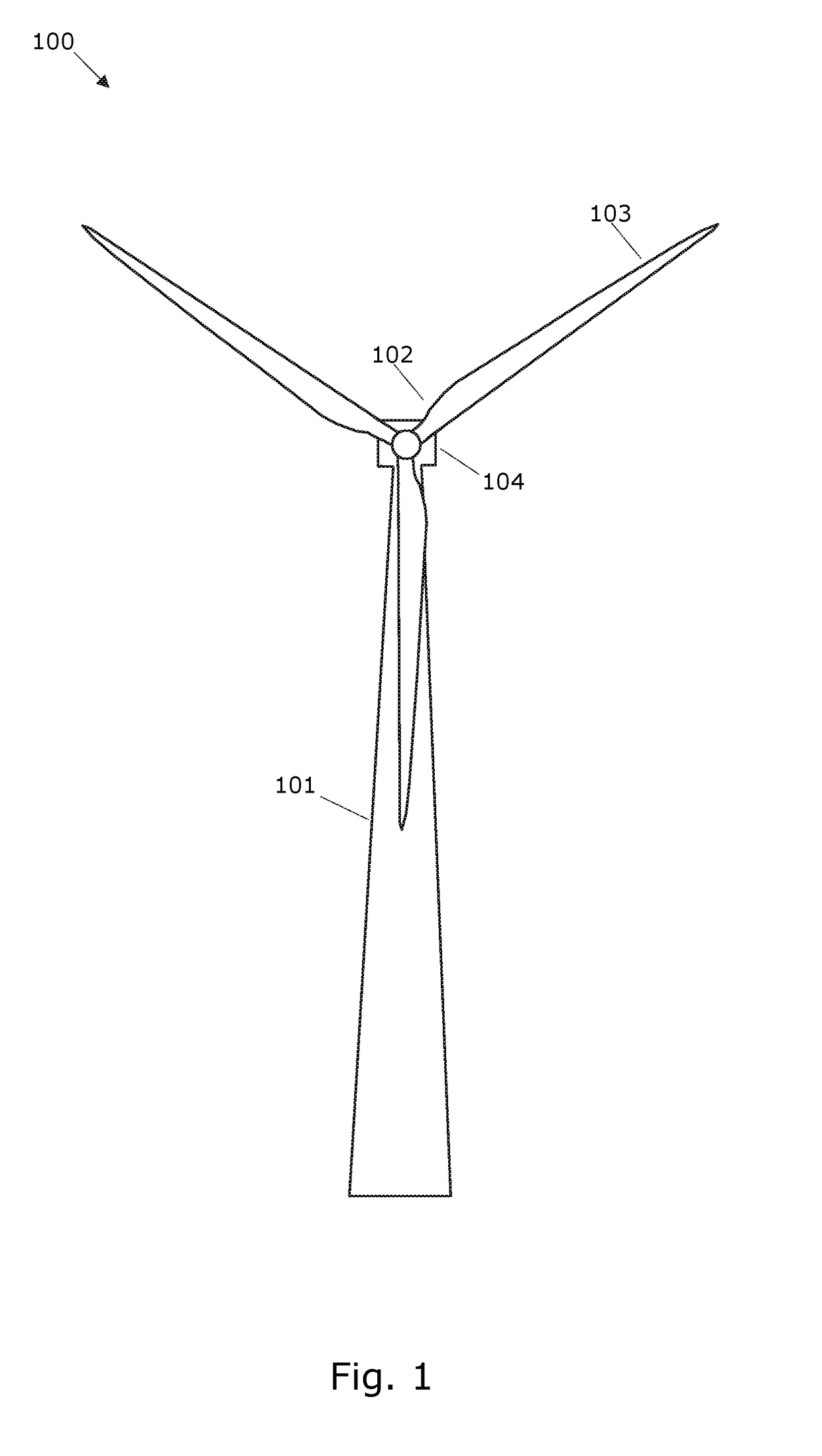
[0041]FIG. 1 shows a wind turbine 100 comprising a tower 101 and a rotor 102 with at least one rotor blade 103, such as three blades. The rotor is connected to a nacelle 104 which is mounted on top of the tower 101 and being adapted to drive a generator situated inside the nacelle. The rotor 102 is rotatable by action of the wind. The wind induced rotational energy of the rotor blades 103 is transferred via a shaft to the generator. Thus, the wind turbine 100 is capable of converting kinetic energy of the wind into mechanical energy by means of the rotor blades and, subsequently, into electric power by means of the generator. In this document the wind turbine 100 may also be referred to with the common abbreviation WTG (Wind Turbine Generator).

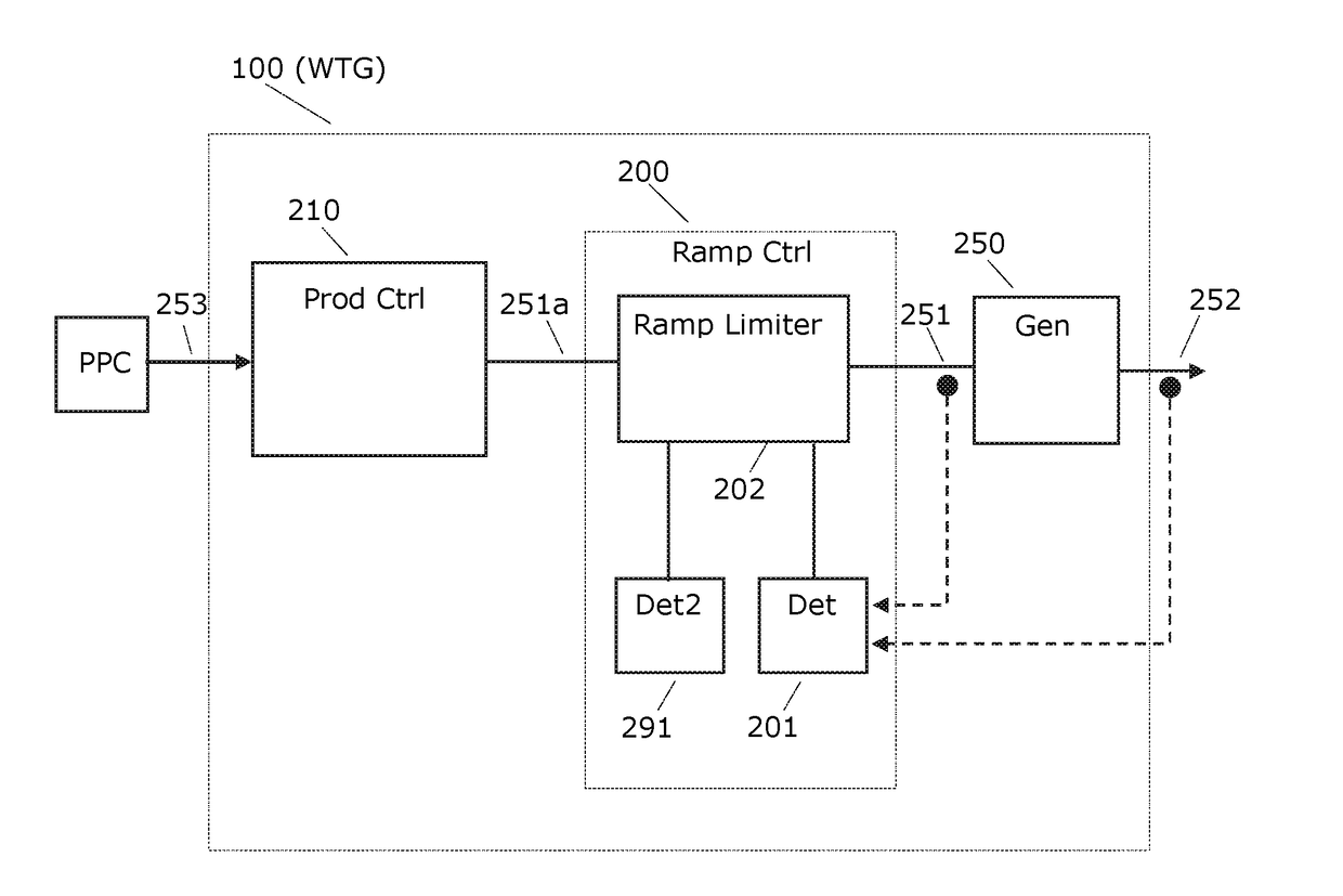
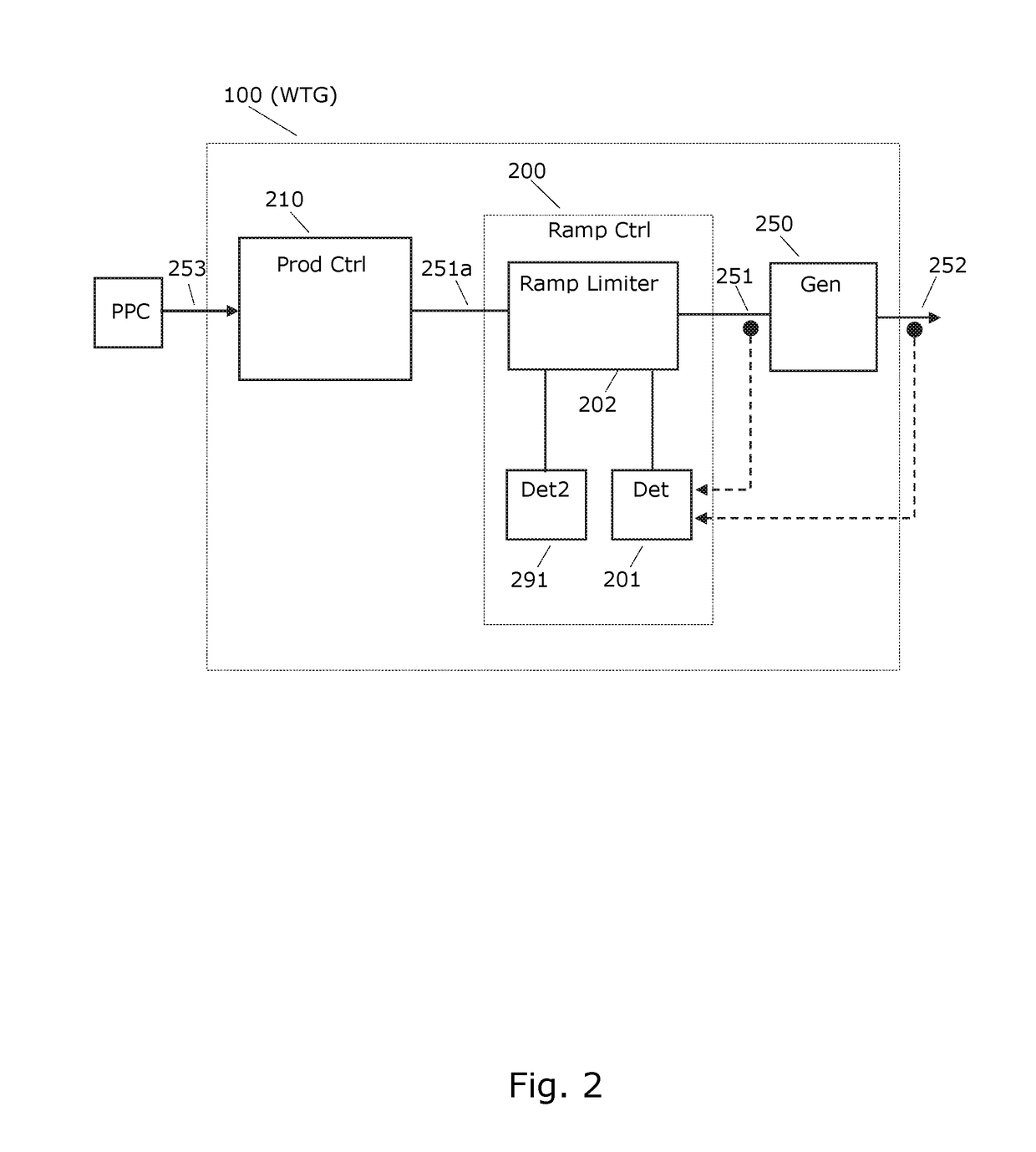
[0042]Structural components of the wind turbine such as the tower may be influenced by forces created due to changes in the power set point, i.e. when the generator is controlled to change the amount of produced power. Such structural oscillat...


PUM


Abstract

The invention relates to a method for limiting structural loads in a wind turbine in situations where the power produced by the wind turbine is increased or decreased. The limitation of structural loads is achieved by restricting the power ramp rate, i.e. the rate of change of increases or decreases in produced power. The restriction is only invoked if a maximum change of the produced power or the corresponding internal power reference within a time window exceeds a given threshold.

Description

FIELD OF THE INVENTION[0001]The invention relates to control of wind turbines, particularly to control of wind turbines in connection with power ramp rates.BACKGROUND OF THE INVENTION[0002]Power ramping requirements originating from grid codes may be in conflict with protection of the mechanical components of wind turbines. Tower oscillations may be excited if a wind turbine follows a request to ramp the active power with large amplitude and high ramp rate. Tower oscillations may reduce the life-time of the wind turbine and should therefore be avoided as much as possible. As grid codes may set higher requirements to wind turbine's ability to change power from one set-point to another set-point, the structural requirements, e.g. in terms of the mechanical strength of the tower or other wind turbine components, may increase.[0003]Accordingly, there is a need to improve the capability of wind turbines to handle power ramping requirements.[0004]WO2013044927 discloses a method for operat...

Claims


Application Information

Patent Timeline
IPC IPC(8): F03D7/02H02P9/10H02J3/38F03D9/25F03D80/80H02K7/18
CPCF03D7/028F03D9/25F03D80/82H02J3/386H02P9/105H02K7/1838F05B2240/912F05B2270/331Y02E10/728H02J2300/28H02J3/381Y02E10/76Y02E10/72F05B2270/1033F05B2270/309F05B2270/335
Inventor KJ R, MARTIN ANSBJERGTHOMSEN, JESPER SANDBERGGRON-STEVENS, ROBERT
Owner VESTAS WIND SYST AS
Why Eureka
Try Eureka