Clamp coupling and method of fastening the same

a technology of clamping and clamping segments, which is applied in the direction of mechanical equipment, manufacturing tools, machines/engines, etc., can solve the problems of reducing the spring force of the clamp segment, reusing the clamping coupling, and unsuitable reuse of the clamping coupling, so as to reduce the spaced distance and shorten the circumferential length of the clamping segmen

Active Publication Date: 2017-11-16
TOYOTA IND CORP
View PDF4 Cites 9 Cited by
  • Summary
  • Abstract
  • Description
  • Claims
  • Application Information

AI Technical Summary

Benefits of technology

[0005]In accordance with a first aspect of the present invention, there is provided a clamp coupling including a plurality of clamp segments including respective grooves each having a U or V sectional shape and a connecting section having a first connecting section and a second connecting section for connecting the clamp segments. The plural clamp segments are connected in a ring shape with the groove facing inward of the ring shape. The clamp segments are configured to hold a plurality of objects to be connected in the grooves and connect the objects. The first connecting section is configured to serve as a hinge that permits the clamp segments to be opened from and closed to the ring shape. The second connecting section is configured to connect the plural clamp segments and to permit adjustment of a circumferential length of the plural clamp segments having the ring shape, wherein the second connecting section includes a fastening section and a contact section disposed outward of the ring shape from the fastening section. The contact section connects the clamp segments at one ends thereof in direct or indirect contact with each other and includes a changing means to change a spaced distance between the one ends of the clamp segments. The fastening section includes an externally threaded body inserted through the one ends and an internally threaded body screwed with the externally threaded body for holding the one ends and fastening the clamp segments thereby to reduce the spaced distance between the one ends of the clamp segments and connect the objects held in the grooves.
[0006]In accordance with a second aspect of the present invention, there is provided a method of fastening a clamp coupling. The clamp coupling includes a plurality of clamp segments including respective grooves each having a U or V sectional shape and a connecting section having a first connecting section and a second connecting section for connecting the clamp segments. The plural clamp segments are connected in a ring shape with the groove facing inward of the ring shape. The clamp segments are configured to hold a plurality of objects to be connected in the grooves and connect the objects. The first connecting section is configured to serve as a hinge that permits the clamp segments to be opened from and closed to the ring shape. The second connecting section is configured to connect the plural clamp segments and to permit adjustment of a circumferential length of the plural clamp segments having the ring shape, wherein the second connecting section includes a fastening section and a contact section disposed outward of the ring shape from the fastening section. The contact section connects the clamp segments at one ends thereof in direct or indirect contact with each other and includes a changing means to change a spaced distance between the one ends of the clamp segments. The fastening section includes an externally threaded body inserted through the one ends and an internally threaded body screwed with the externally threaded body for holding the one ends and fastening the clamp segments thereby to reduce the spaced distance between the one ends of the clamp segments and connect the objects held in the grooves. The method includes holding the shim as the changing means in the contact section between the one ends of the clamp segments in a case that adjustment is made so that the circumferential length of the plural clamp segments connected in the ring shape is increased and removing the shim from the contact section so that the one ends of the clamp segments are brought into direct contact with each other in a case that adjustment is made so that the circumferential length of the clamp segments is shortened.

Problems solved by technology

However, there are problems in reusing the clamp coupling.
If the clamp coupling holding the flange portions of the cylindrical cases is exposed to heat of exhaust gas through the cylindrical cases, creep occurs in the clamp coupling, so that spring force of the clamp segments is reduced and such insufficient spring force renders the clamp coupling inappropriate for reuse.

Method used


Image

  • Clamp coupling and method of fastening the same
  • Clamp coupling and method of fastening the same
  • Clamp coupling and method of fastening the same

Examples


Embodiment Construction

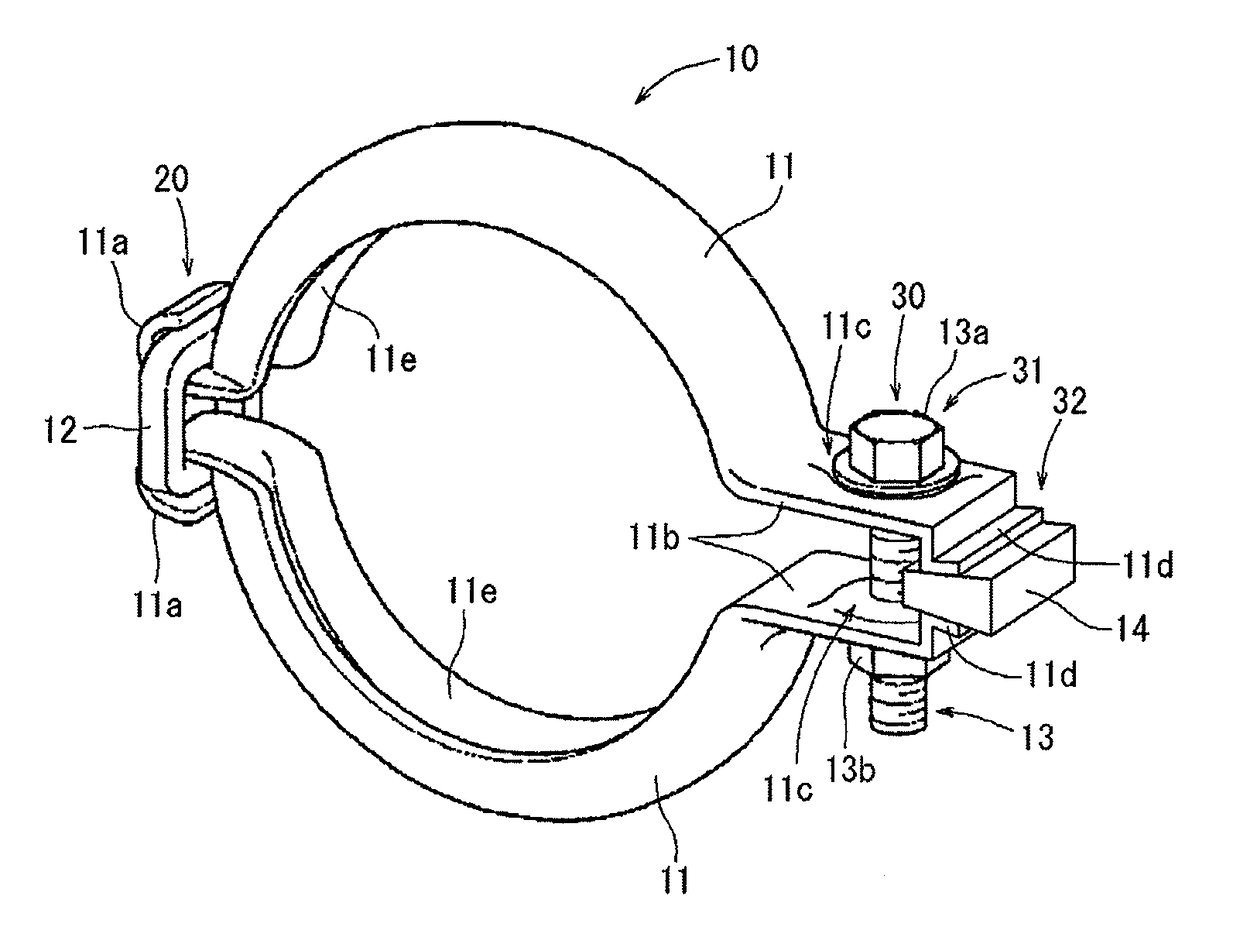
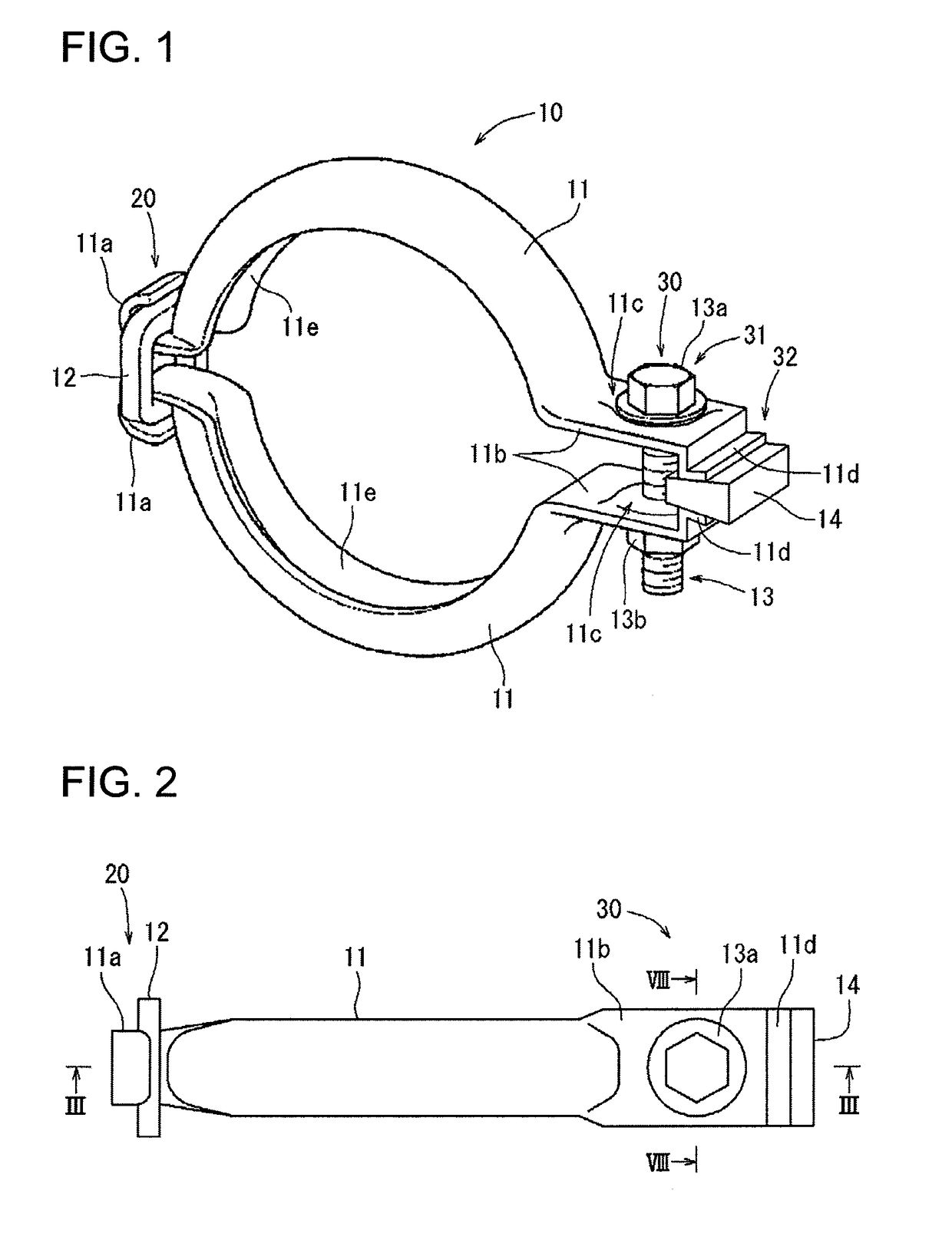
[0023]The following will describe a clamp coupling according to an embodiment of the present invention with reference to FIGS. 1 to 8. Referring to FIG. 1, there is shown a clamp coupling 10. The clamp coupling 10 includes a pair of clamp segments 11 that are combined to form a ring shape. Each clamp segment 11 has a groove 11e that has a U-shaped section and faces inward of the ring shape. The clamp segment 11 is made of spring steel. It is noted that the groove 11e may have a V-shaped section. As will be described later, the clamp coupling 10 holds a plurality of objects in the grooves 11e and connects the objects.

[0024]The paired clamp segments 11 are connected at the ends thereof by two connecting sections including a first connecting section 20 and a second connecting section 30. The first connecting section 20 of the clamp coupling 10 is configured to serve as a hinge that permits the paired clamp segments 11 to be opened to receive therein objects to be connected and to be cl...


PUM

PropertyMeasurementUnit
circumferential lengthaaaaaaaaaa
distanceaaaaaaaaaa
spring forceaaaaaaaaaa

Abstract

A clamp coupling includes clamp segments and a connecting section including a fastening section and a contact section. The contact section connects the clamp segments and includes a changing means to change a spaced distance between the clamp segments. The fastening section includes an externally threaded body and an internally threaded body for holding the clamp segments thereby to reduce the spaced distance between the clamp segments and connect objects. A method of fastening the clamp coupling includes holding the shim in the contact section between one ends of the clamp segments in a case that adjustment is made so that a circumferential length of the clamp segments is increased and removing the shim from the contact section so that the clamp segments are brought into direct contact with each other in a case that adjustment is made so that the circumferential length of the clamp segments is shortened.

Description

BACKGROUND OF THE INVENTION[0001]The present invention relates to a clamp coupling that connects a plurality of objects to be connected with each other by holding the connecting objects in a circular groove and also to a method of fastening the clamp coupling.[0002]In a diesel particulate filter (hereinafter referred to as DPF) for purifying exhaust gas discharged from a diesel engine, oil-derived calcium compound substance is deposited in the filter. In order to maintain the desired purifying performance of the DPF, it needs to be cleaned for refreshment. Japanese Patent Application Publication No. 2003-120277 discloses a device for purifying exhaust gas from an internal combustion engine. The DPF which is accommodated in a cylindrical case needs to be removed therefrom for cleaning of the DPF. For this purpose, the cylindrical case is configured to include two halves that are separable from each other. Each cylindrical case half has a circular flange portion and the cylindrical ca...

Claims


Application Information

Patent Timeline
Patent Type & Authority Applications(United States)
IPC IPC(8): F16L23/08
CPCF16L23/08F01N13/1844F01N3/0211F01N13/1855Y10T29/49398Y10S29/003Y10T24/1443Y10T24/1445F16B2/065F01N3/035
Inventor MOTOYAMA, YUTO
Owner TOYOTA IND CORP
Why Eureka
Try Eureka