Micro-channel heat exchanger

a heat exchanger and microchannel technology, applied in indirect heat exchangers, refrigeration components, light and heating equipment, etc., can solve the problems of reducing the area of a heat exchange zone, increasing the cost, and reducing the heat exchange efficiency of the heat exchanger, so as to reduce the manufacturing difficulty, the effect of saving space and reducing costs

Active Publication Date: 2017-11-16
ZHEJIANG DUNAN THERMAL SCI & TECH
View PDF8 Cites 9 Cited by
  • Summary
  • Abstract
  • Description
  • Claims
  • Application Information

AI Technical Summary

Benefits of technology

[0016]According to the micro-channel heat exchanger provided by the present invention, since each of the plate-type header pipe comprises a flat tube groove plate and a distribution and the round header pipes are manufactured into a structure consisting of a plurality of plates which are stacked, the space can be saved, the cost is reduced, the manufacturing difficulty is reduced, the proportion of the windward area occupied by the header pipes is reduced, the area of the non-heat-exchange unit can be decreased, the proportion of the heat exchange area occupied in the heat exchanger is increased and the heat exchange efficiency of the heat exchanger is improved.

Problems solved by technology

Moreover, when the windward size of the micro-channel heat exchanger is limited, the header pipe as a non-heat-exchange unit will occupy certain area, consequently the area of a heat exchange zone is decreased and the heat exchange efficiency of the heat exchanger is reduced; and especially when the flat tubes are relatively wide, the diameter of the header pipe will be increased correspondingly, consequently the cost is increased and the heat exchange area is further decreased.

Method used


Image

  • Micro-channel heat exchanger
  • Micro-channel heat exchanger
  • Micro-channel heat exchanger

Examples


embodiment 1

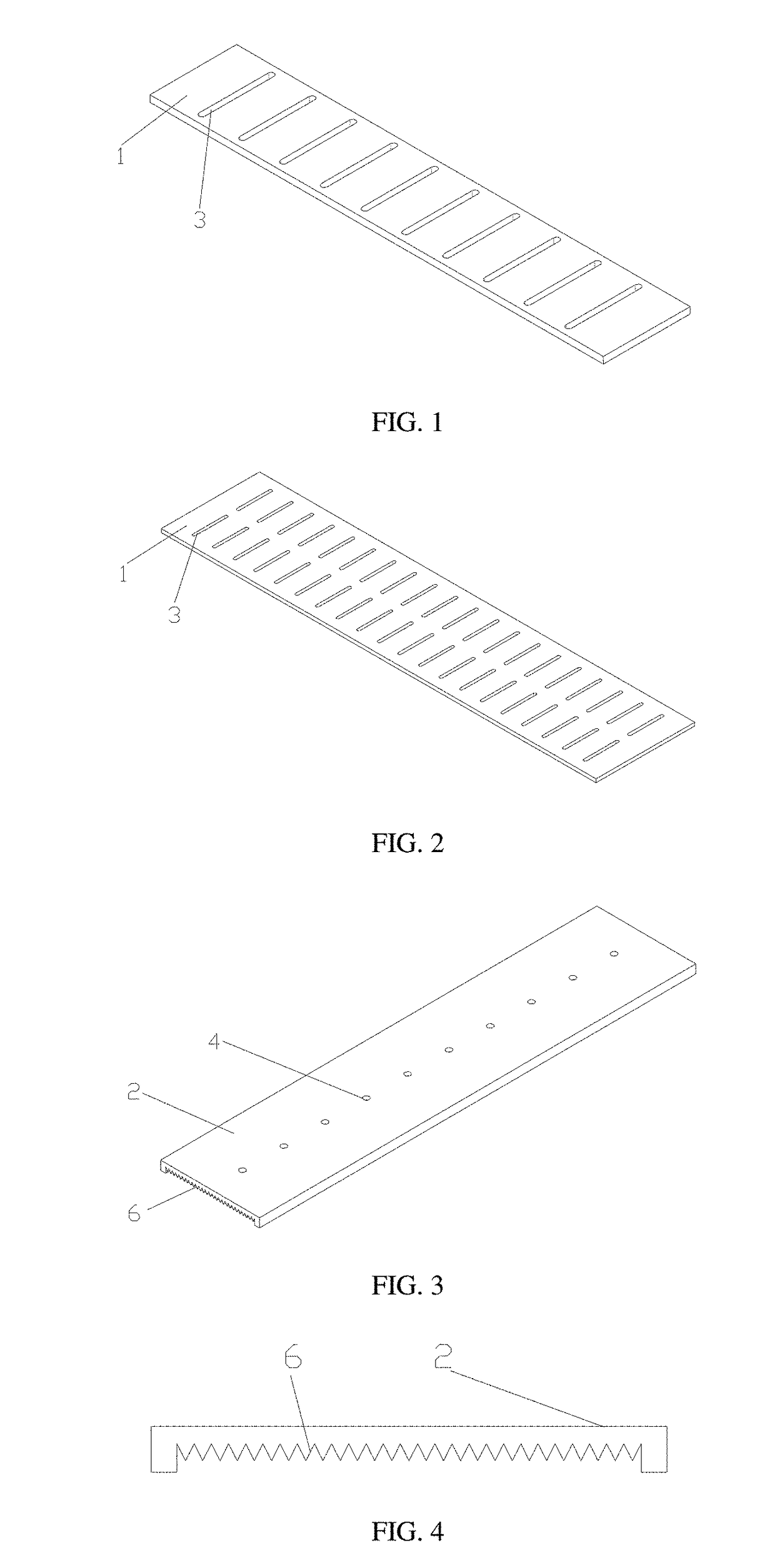
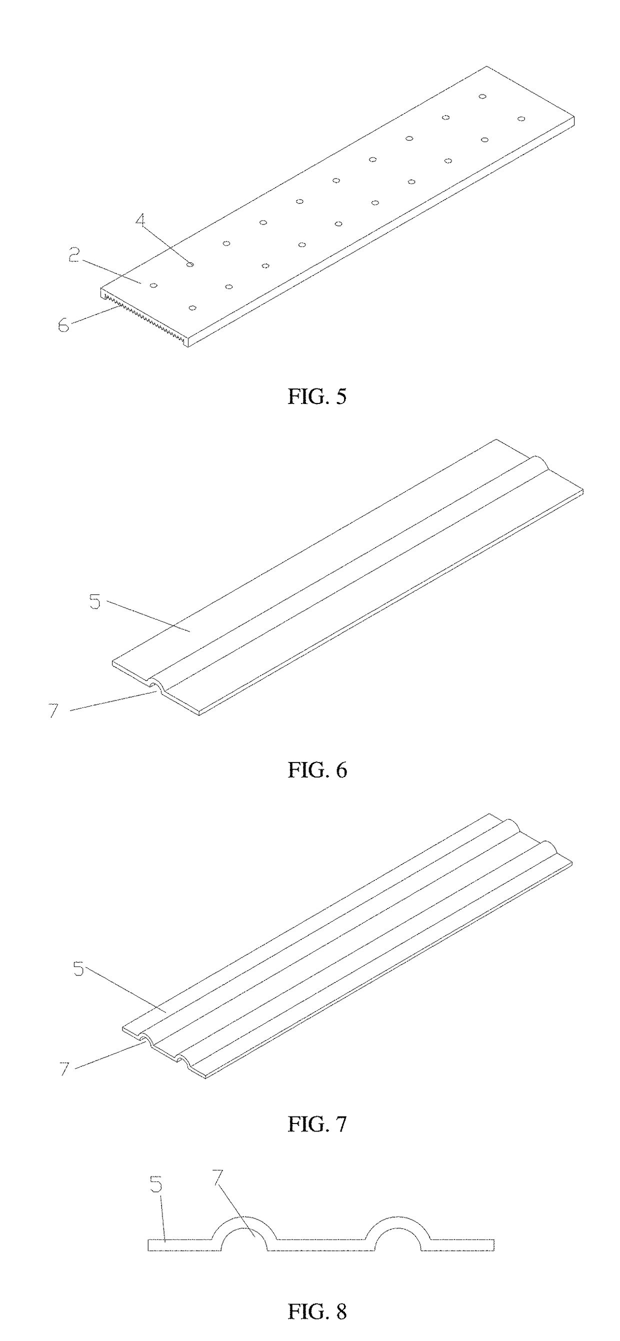
[0060]As illustrated in FIG. 9 and FIG. 10, a plate-type header pipe of the present invention comprises a flat tube groove plate 1 having flat tube groove through holes 3 in a single column, a distribution plate 2 having distribution holes in a single column and an outer side sealing plate having a protruding channel 7. The three plates are closely sealed and combined together. The refrigerant firstly enters the protruding channel 7, then is uniformly distributed through the distribution holes in the distribution plate 2 in a process of flowing in the protruding channel 7, then enters circulation channels formed by toothed grooves 6 in the distribution plate 2 and the flat tube groove plate 1 and flows in the circulation channels. Since the section size (hydraulic diameter) of the toothed grooves 6 is small, gas-liquid separation can be effectively avoided.

[0061]After the refrigerant is uniformly mixed through the resistance of the toothed grooves 6, the refrigerant is distributed ...

embodiment 2

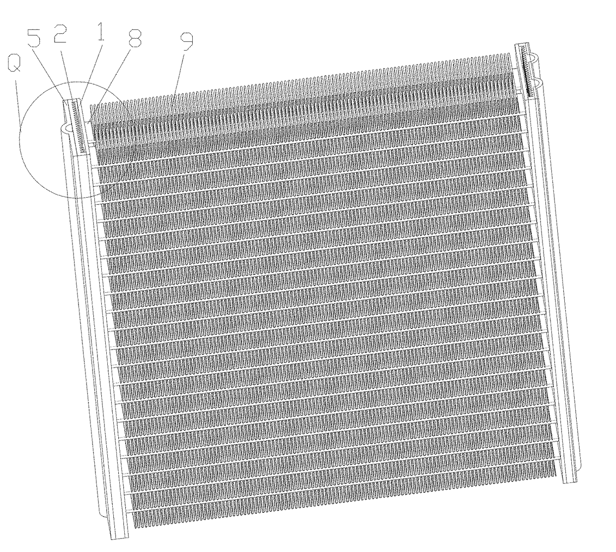
[0067]As illustrated in FIG. 11, of the present invention, the flat tube groove through holes 3, the distribution channels 11 and the throttling channels 4 are all provided in a single column, each of the distribution channels 11 is provided corresponding to the flat tube groove through holes 3 in two rows, each of the throttling channels 4 is provided corresponding to one distribution channel 11, and the throttling channels 4 here are throttling holes. The structure of the plate-type header pipes at two ends of the flat tubes 8 is the same, thereby forming a single-row single-pass micro-channel heat exchanger.

embodiment 3

[0068]As illustrated in FIG. 12, of the present invention, the flat tube groove through holes 3, the distribution channels 11 and the throttling channels 4 are all provided in a single column, each of the distribution channels 11 in the plate-type header pipe at one end of the flat tubes 8 is provided corresponding to the flat tube groove through holes 3 in two rows, each of the throttling channels 4 is provided corresponding to one distribution channel 11, and the throttling channels 4 here are throttling holes. The number of the distribution channels 11 in the plate-type header pipe in the other end of the flat tubes 8 is two, and each of the distribution channels 11 is provided corresponding to the flat tube groove through holes 3 in a plurality of rows, thereby forming a single-row multi-pass micro-channel heat exchanger.


PUM


Abstract

The invention involves a micro-channel heat exchanger, which includes flat tubes (8), fins(9) and plate-type header pipes communicated with the flat tubes, (8) each plate-type header pipe comprising a flat tube groove plate, a distribution plate (2) and an outer side sealing plate (5), a plurality of flat tube groove through holes (3) are provided in the flat tube groove plate (1) along a length direction, throttling channels (4) communicated with the flat tube groove through holes (3) are provided in the distribution plate (2) along an arrangement direction of the flat tube groove through holes (3), the outer side sealing plate (5) is provided on one side, far away from the flat tube groove plate (1), of the distribution plate (2). The micro-channel heat exchanger can solve the problems of low heat exchange efficiency and small heat exchange area of the heat exchanger.

Description

CROSS REFERENCE TO RELATED APPLICATION[0001]This application claims priority to Chinese Patent Application No. 201610318160.X, filed on May 13, 2016, the entire contents of which are incorporated herein by reference.FIELD OF THE INVENTION[0002]The present invention relates to a heat exchanger assembled and used in an air conditioner, a refrigerator, a heat pump or the like, in particular to a micro-channel heat exchanger.BACKGROUND OF THE INVENTION[0003]The existing micro-channel heat exchanger usually consists of three major parts, i.e., flat tubes, fins and header pipes, wherein the header pipes are usually round and are mainly used for distributing and collecting refrigerant in the flat tubes.[0004]Since the internal spaces of the round header pipes are relatively great, gas refrigerant and liquid refrigerant inside the round header pipes are caused to be separated, consequently the uniform distribution of the refrigerant in the flat tubes is seriously influenced, and usually liq...

Claims


Application Information

Patent Timeline
Patent Type & Authority Applications(United States)
IPC IPC(8): F28D1/053F28F1/12F28F9/02
CPCF28D1/05366F28D1/05383F28F1/126F28F9/0278F28F9/0273F28F2260/02F25B39/00F28F9/02F28F9/0221F28F9/0243
Inventor WU, QINGHAOJIANG, JUNYU, HUANGANG
Owner ZHEJIANG DUNAN THERMAL SCI & TECH
Why Eureka
Try Eureka