Eureka AIR delivers breakthrough ideas for toughest innovation challenges, trusted by R&D personnel around the world.

Signal Control Circuit, Power Control Circuit, Drive Circuit, Timing Controller, Touch System, and Touch Display Device and Driving Method Thereof

a technology of power control circuit and drive circuit, which is applied in the direction of electric digital data processing, instruments, computing, etc., can solve the problems of increasing the load of the touch driving, degrading the accuracy of the touch sensing, and generating unnecessary parasitic capacitance, so as to achieve the effect of eliminating parasitic capacitan

Active Publication Date: 2017-11-16
LG DISPLAY CO LTD
View PDF1 Cites 11 Cited by
  • Summary
  • Abstract
  • Description
  • Claims
  • Application Information

AI Technical Summary

Benefits of technology

The present invention relates to a touch display device and a driving method thereof, which can effectively remove parasitic capacitance and prevent it from being generated in the whole area of the device. Additionally, the invention can effectively generate various types of signals required for a load free driving signal for touch driving and for preventing parasitic capacitance. The technical effect of the invention is to improve the accuracy and stability of touch display device.

Problems solved by technology

Meanwhile, during touch driving and sensing, unnecessary parasitic capacitance may be generated in addition to capacitance necessary for the touch sensing.
In the capacitance touch methods, the unnecessary parasitic capacitance may increase a load of the touch driving, degrade the accuracy of the touch sensing, or make the touch sensing itself impossible in severe cases.
The problems caused by the unnecessary parasitic capacitance may be more serious in the case of display devices that have a Touch Screen Panel (TSP) embedded in a display panel thereof.

Method used


Image

  • Signal Control Circuit, Power Control Circuit, Drive Circuit, Timing Controller, Touch System, and Touch Display Device and Driving Method Thereof
  • Signal Control Circuit, Power Control Circuit, Drive Circuit, Timing Controller, Touch System, and Touch Display Device and Driving Method Thereof
  • Signal Control Circuit, Power Control Circuit, Drive Circuit, Timing Controller, Touch System, and Touch Display Device and Driving Method Thereof

Examples


Embodiment Construction

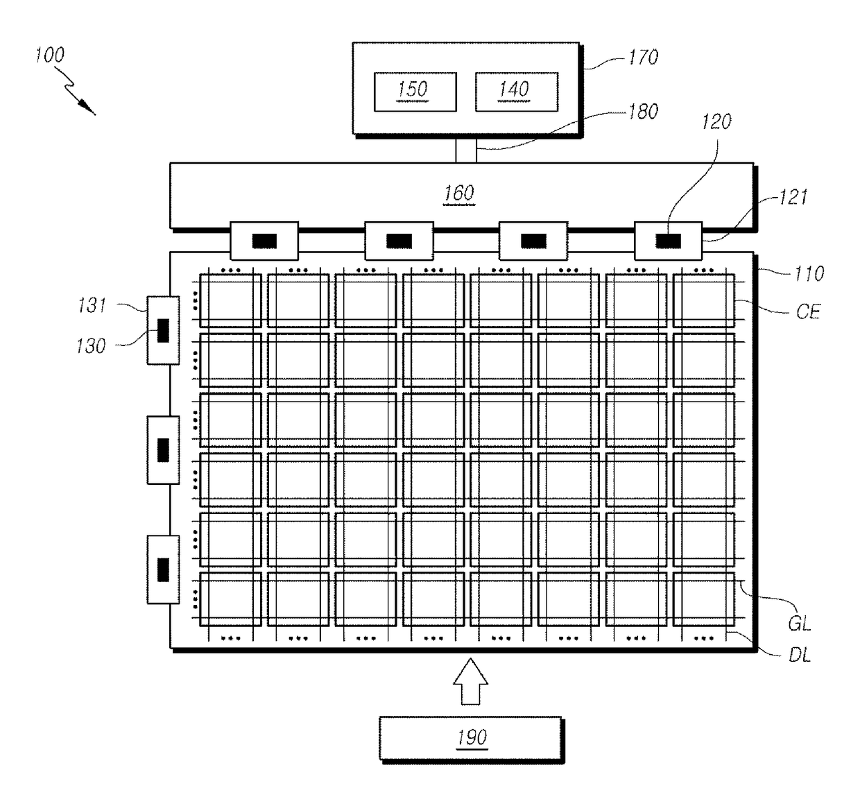
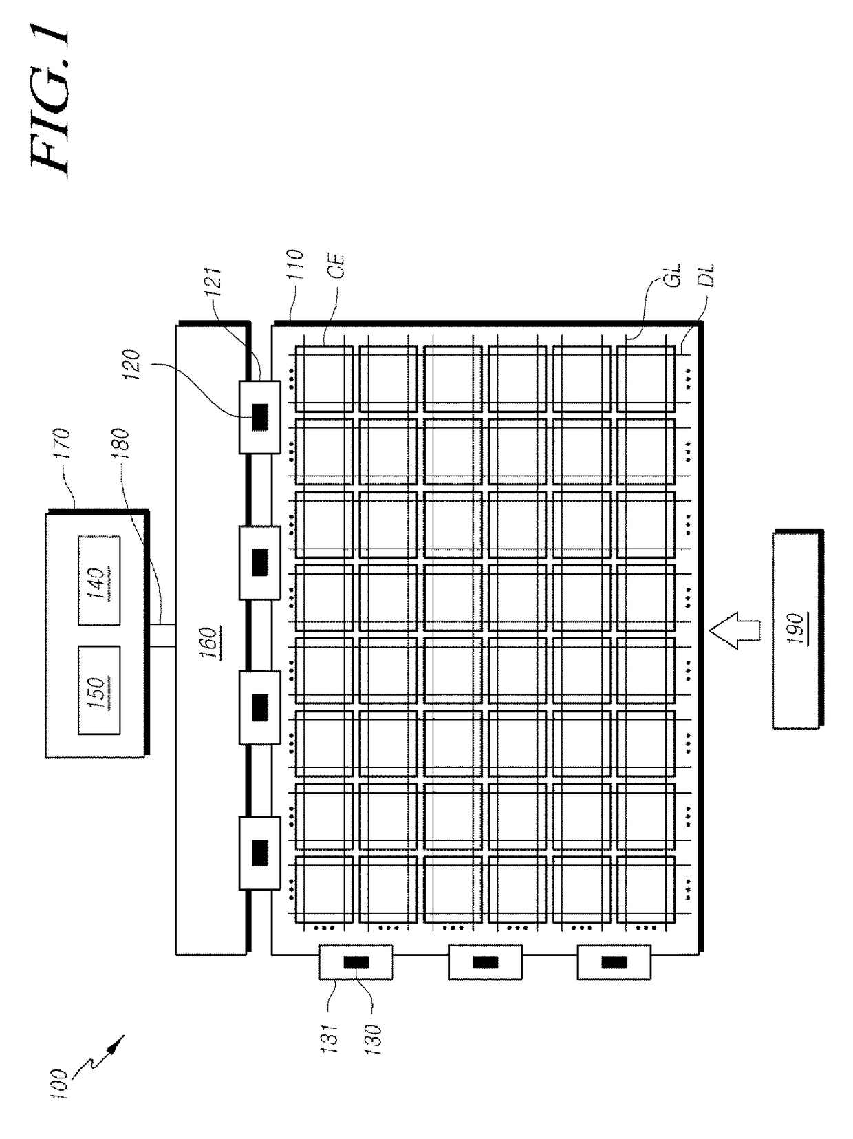
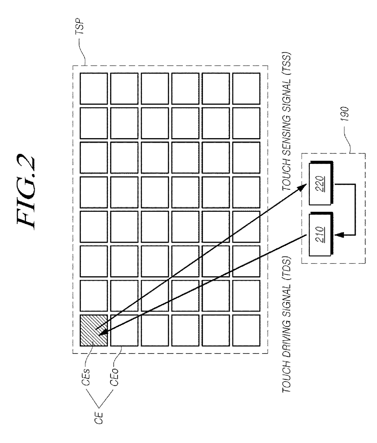
[0072]Hereinafter, exemplary embodiments of the present invention will be described in detail with reference to the accompanying drawings. In designating elements of the drawings by reference numerals, the same elements will be designated by the same reference numerals although they are shown in different drawings. Further, in the following description of the present invention, a detailed description of known functions and configurations incorporated herein will be omitted when it may make the subject matter of the present invention rather unclear.

[0073]In addition, terms, such as first, second, A, B, (a), (b) or the like may be used herein when describing components of the present invention. Each of these terminologies is not used to define an essence, order or sequence of a corresponding component but used merely to distinguish the corresponding component from other component(s). In the case that it is described that a certain structural element “is connected to”, “is coupled to”,...


PUM

PropertyMeasurementUnit
voltageaaaaaaaaaa
voltagesaaaaaaaaaa
ground voltageaaaaaaaaaa

Abstract

Exemplary embodiments of the present invention relate to a touch technology, and more specifically, to a signal control circuit, a power control circuit, a drive circuit, a timing controller, a touch system, and a touch sensitive display device and a driving method thereof that can simply swing various voltages in a display device for a touch mode period by using a modulated ground voltage obtained by swinging a ground voltage, thereby effectively providing touch driving and preventing unnecessary parasitic capacitance from being generated not only in an active area but also in all other areas.

Description

CROSS-REFERENCE TO RELATED APPLICATION[0001]This application is a continuation of U.S. patent application Ser. No. 14 / 984,657 filed on Dec. 30, 2015, which claims priority from and the benefit under 35 U.S.C. §119(a) of Republic of Korea Patent Application No. 10-2015-0142532, filed on Oct. 13, 2015, and also claims priority from Republic of Korea Patent Application No. 10-2015-0185479, filed on Dec. 23, 2015, all of which are hereby incorporated by reference for all purposes as if fully set forth herein.BACKGROUND1. Field of the Disclosure[0002]Exemplary embodiments relate to a signal control circuit, a power control circuit, a drive circuit, a timing controller, a touch system, and a touch display device and a driving method thereof.2. Description of the Prior Art[0003]With the development of the information society, display devices for displaying images are being increasingly required in various forms, and in recent years, various display devices, such as Liquid Crystal Displays ...

Claims


Application Information

Patent Timeline
Patent Type & Authority Applications(United States)
IPC IPC(8): G02F1/1333G02F1/1343G06F3/041G06F3/044
CPCG02F1/13338G06F3/044G02F1/1343G06F3/0412G06F2203/04112G06F2203/04111G06F3/0418G06F3/04166G06F3/0443G09G3/20G09G2300/0838G09G2310/0297G06F3/041
Inventor KIM, SUNGCHULJANG, HYUNGUKBAE, SANGHYUCKHAN, SUNGSUJU, SUYUNJUNG, DOYOUNG
Owner LG DISPLAY CO LTD
Why Eureka
Eureka Blog
Learn More