Aerofoil body with integral curved spar-cover

a spar-covering and aerosol technology, applied in the field of aerosol wing or winglet, can solve the problems of weight, complexity and cost, and achieve the effects of reducing carbon emissions, reducing drag on the wing, and improving fuel efficiency

Active Publication Date: 2017-11-23
AIRBUS OPERATIONS LTD
View PDF0 Cites 5 Cited by
  • Summary
  • Abstract
  • Description
  • Claims
  • Application Information

AI Technical Summary

Benefits of technology

[0011]The invention is advantageous in that the spar and cover can be integrally formed, reducing parts count compared with a conventional aerofoil body have separately manufactured spars and covers which are assembled together. For conformity of the composite laminate material through the fold region without ‘ply spread’ or ‘ply bunching’ the resulting spar and cover both necessarily have curvature. In planform (i.e. vertically from above along the z-axis of a cartesian coordinate system) the spar of the aerofoil shaped body is curved. Looking aft (i.e. horizontally from in front along the x-axis) the cover of the aerofoil shaped body has dihedral (or anhedral) curvature. The spar has no kink The invention improves manufacturability.
[0025]Theoretically where the angle between the cover and spar of the spar-cover is exactly 90 degrees and the corner has zero radius, the sweep angle curvature of the spar will equal the di / anhedral curvature of the cover. However, in practice the corner must have a non-zero radius for ply continuity through the corner. By varying the angle between the cover and the spar, and by varying the radius of the corner the correlation between the sweep angle curvature of the spar will equal the di / anhedral curvature of the cover can be varied. The angle between the cover and the spar, and the radius of the corner, may be constant along the fold region in the longitudinal direction, or one or both of these parameters may vary in the longitudinal direction to give maximum flexibility in the design of the shape of the aerofoil shaped body.
[0030]A wing tip device is attached to the outboard end of a wing to reduce induced drag on the wing. In the case of e.g. an aircraft wing this can lead to improved fuel efficiency and reduced carbon emissions. Wing tip devices can take a variety of forms. A winglet is a wing-like element that extends from the wing tip, and may extend upwardly or downwardly from the wing tip. A downwardly extending winglet is more generally known as a ‘downlet’. Another example of a wing tip device is a non-planar wing tip extension, i.e. it extends out of the plane of the wing to which it is attached. A winglet may be considered to be a particular example of a non-planar wing tip extension.

Problems solved by technology

Nevertheless a kinked spar still comprises two substantially straight portions either side of the kink The joints between the straight spar sections typically necessitates joint plates which add weight, complexity and cost.

Method used


Image

  • Aerofoil body with integral curved spar-cover
  • Aerofoil body with integral curved spar-cover
  • Aerofoil body with integral curved spar-cover

Examples


Embodiment Construction

)

[0047]FIG. 1 illustrates a typical configuration for a fixed wing passenger transonic jet transport aircraft 1. The aircraft 1 comprises a fuselage 2, wings 3, main engines 4, and horizontal and vertical tail planes 5, 6. It will be appreciated that this invention is applicable to a wide variety of aircraft types not just that illustrated in FIG. 1. For example, the aircraft may be for commercial or military purposes, may be for transporting passengers or cargo, may have jet, propeller or other engine propulsion systems, may have a variety of fuselage / wing configurations, e.g. a high wing, low wing or blended wing body, and may be designed to fly at subsonic, transonic or supersonic speeds.

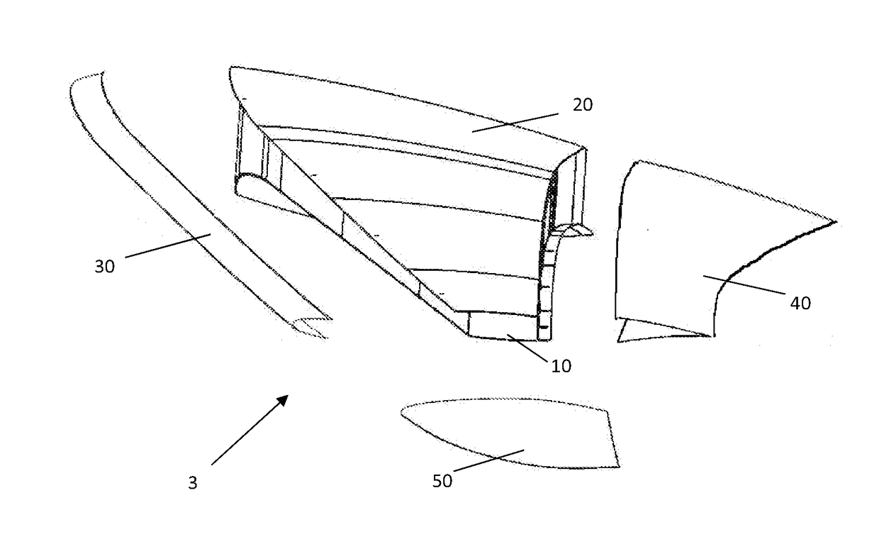
[0048]FIG. 2 illustrates an exploded schematic assembly view of the wing 3 of the aircraft 1. The wing comprises a first spar-cover component 10, a second spar-cover component 20, a leading edge structure 30, a trailing edge structure 40 and a wing tip assembly 50. The wing will typically also in...


PUM

PropertyMeasurementUnit
angleaaaaaaaaaa
angleaaaaaaaaaa
sweep angleaaaaaaaaaa

Abstract

An aerofoil shaped body includes a plurality of longitudinal spars, an upper aerofoil cover, and a lower aerofoil cover. The spars and the covers are made of composite laminate material. One of the spars is integrally formed with one of the covers to form a spar-cover such that the composite laminate material of the spar extends continuously into the cover through a fold region created between the spar and the cover. The fold region has a fold axis extending substantially in the longitudinal direction, and the fold axis projected onto two orthogonal planes has curvature in both those planes.

Description

FIELD OF THE INVENTION[0001]The present invention relates to an aerofoil shaped body; particularly, though not exclusively, an aircraft wing or winglet.BACKGROUND OF THE INVENTION[0002]An aerofoil shaped body is a three dimensional body having an aerofoil cross section (2-D), and is otherwise known as a 3-D aerofoil. Aerofoil bodies typically include a torsion box comprising upper and lower covers (or skins) on either side of a frame comprising spanwise spars and chordwise ribs. At least one spar is provided for each wing, although two or more is more common. In an aircraft wing, the torsion box is otherwise known as a wing box. The covers may also be reinforced with stringers, extending generally spanwise.[0003]Traditionally extensive use has been made of lightweight metallic materials such as Aluminium in aircraft wing design. Mainly for ease of manufacture, the spars are conventionally substantially straight. In recent years there has been a move towards ever increasing use of co...

Claims


Application Information

Patent Timeline
Patent Type & Authority Applications(United States)
IPC IPC(8): B64C3/18B64C3/58B29C70/30B29K105/08B29K307/04B29L31/30
CPCB64C3/185B64C3/58B29L2031/3085B29K2105/0872B29K2307/04B29C70/30B64C3/14B29C70/302B64C1/065B64C1/26B64C3/24Y02T50/40
Inventor WILLIAMS, GEOFFREY RICHARD
Owner AIRBUS OPERATIONS LTD
Why Eureka
Try Eureka