
Data compression apparatus, data decompression apparatus, data compression method, data decompression method, and computer readable medium

a data compression and data compression technology, applied in the field of data compression apparatus, can solve the problems of reducing processing speed and low processing speed, and achieve the effect of improving compression ratio and improving processing speed

Active Publication Date: 2017-11-23
MITSUBISHI ELECTRIC CORP
View PDF4 Cites 1 Cited by
  • Summary
  • Abstract
  • Description
  • Claims
  • Application Information

AI Technical Summary

Benefits of technology

This patent describes a data compression system that combines the use of a high-bit division method and a word-based processing method. The system includes two encoding units that work together to compress the output of an integer division unit. By doing so, the system can achieve both a high compression ratio and high processing speed. In simple terms, this technology allows for faster and more efficient data compression.

Problems solved by technology

That is, since it is difficult to compress the low-order bits with the noise mixed therein, the low-order bits are output as the fixed-length binary data without being compressed.
Thus, there is a problem that compatibility with computer processing is low, leading to reduction of a processing speed.

Method used


Image

  • Data compression apparatus, data decompression apparatus, data compression method, data decompression method, and computer readable medium
  • Data compression apparatus, data decompression apparatus, data compression method, data decompression method, and computer readable medium
  • Data compression apparatus, data decompression apparatus, data compression method, data decompression method, and computer readable medium

Examples


first embodiment

[0034]***Description of Configuration***

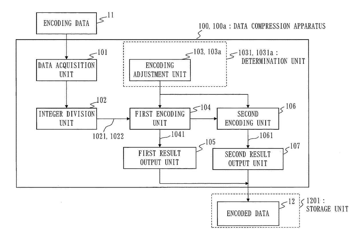
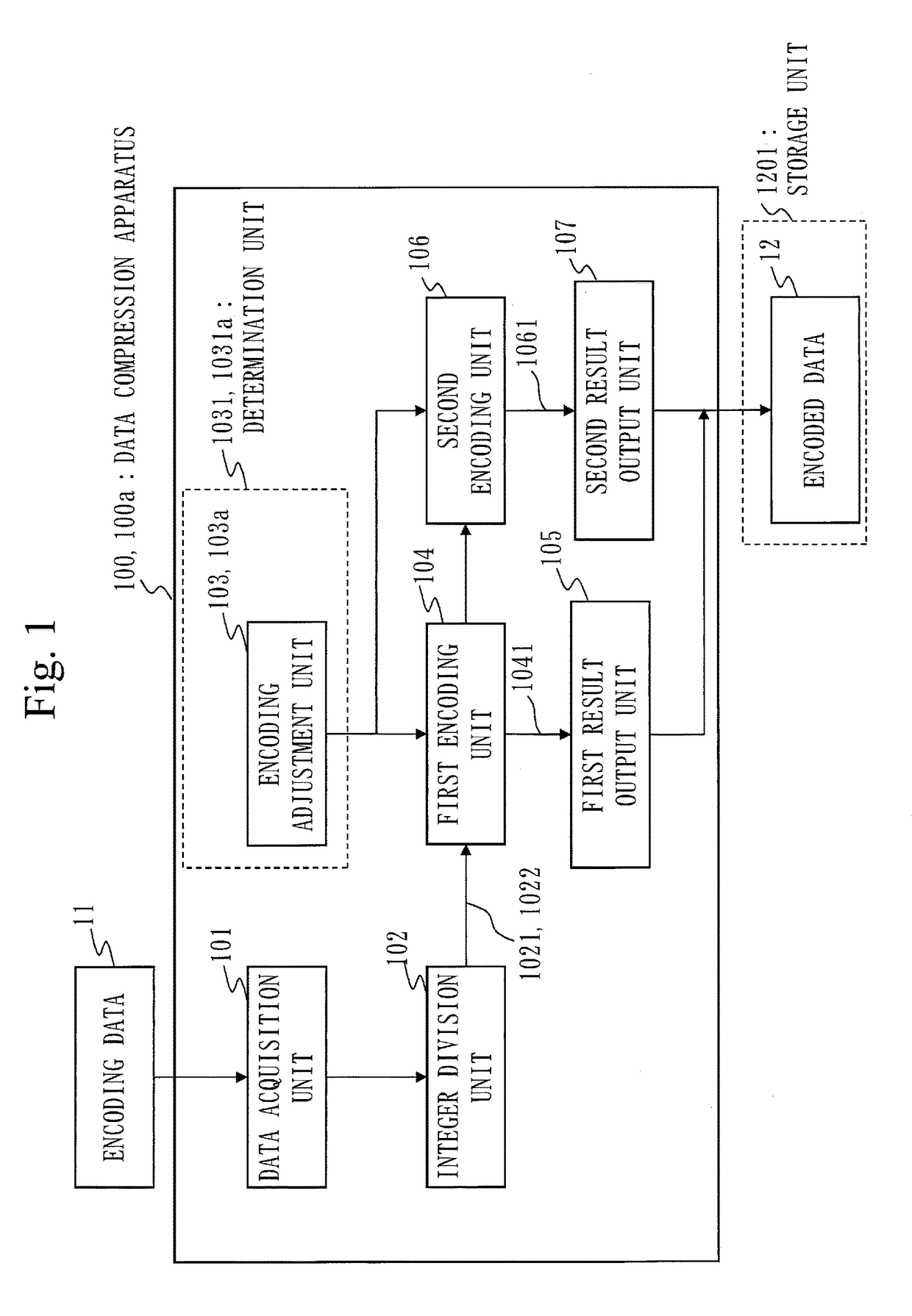
[0035]A block configuration of a data compression apparatus 100 according to this embodiment will be described, using FIG. 1.

[0036]In the following description, the number of unit bits, which is the number of bits for each process is set to L bits. The number of unit bits is also referred to as a word or a byte. The number of unit bits is also referred to as a word unit that is the length of the word.

[0037]The bit length of binary data representing an integer is set to L bits, being equal to the number of unit bits. L is a value such as 16, 32, or 64, but is not limited to these values. This embodiment may be applied to an integer of an arbitrary bit length.

[0038]The data compression apparatus 100 acquires encoding data 11 to be encoded, encodes the encoding data 11 acquired, and stores a result of the encoding in encoded data 12. The encoding data 11 is a string of integers that are placed in order. The number of the integers included in the ...

second embodiment

[0148]In this embodiment, a difference from the first embodiment will be mainly described.

[0149]***Description of Configuration***

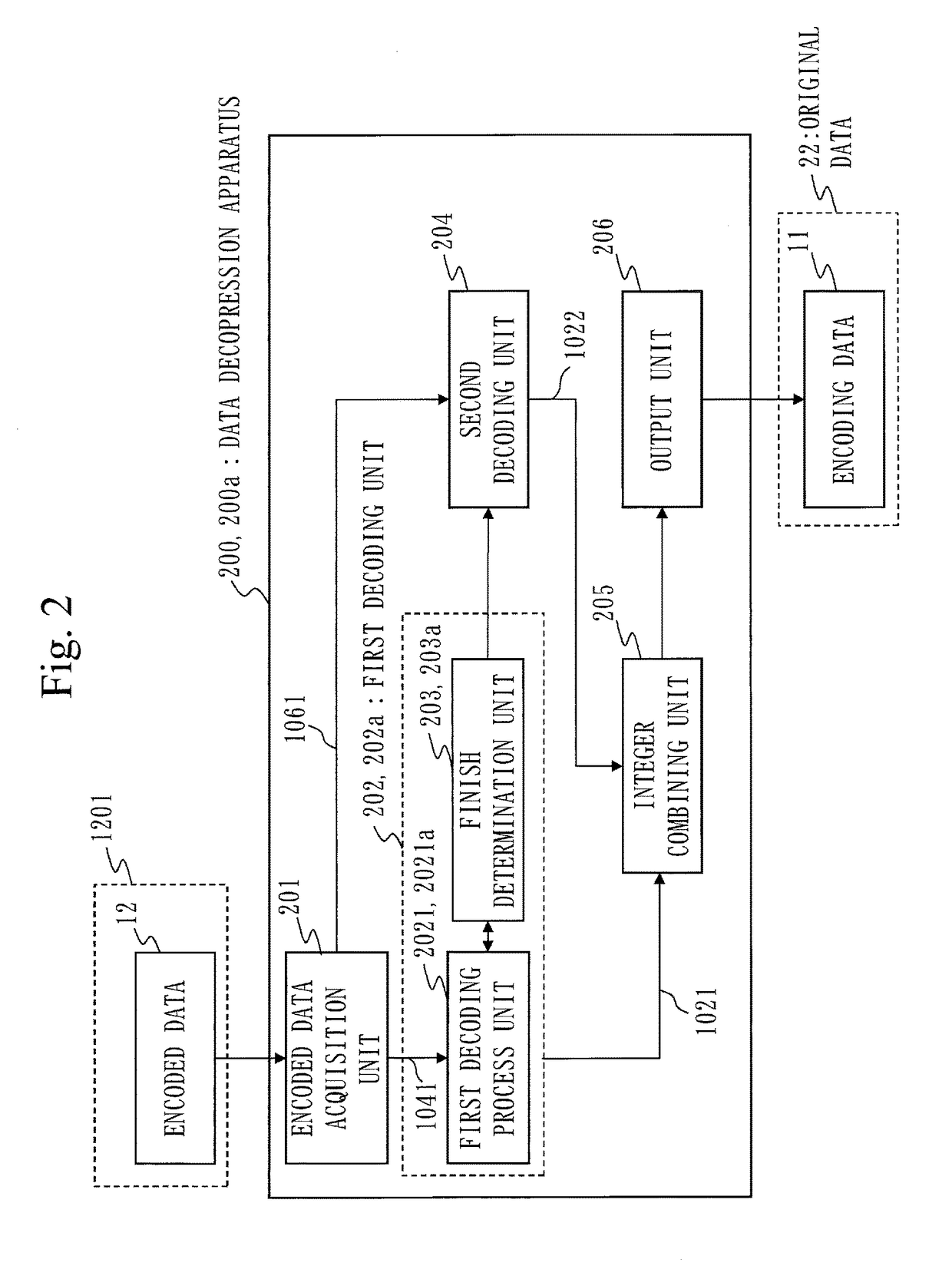
[0150]A block configuration illustrating a data compression apparatus 100a according to this embodiment is given by FIG. 1, as in the first embodiment. A block configuration illustrating a data decompression apparatus 200a according to this embodiment is given by FIG. 2, as in the first embodiment. Description of components that are the same as those described in the first embodiment may be omitted by giving same reference signs to them.

[0151]In the data compression apparatus 100a according to this embodiment, a function and an operation of the encoding adjustment unit 103 are different from those in the first embodiment. In this embodiment, the description will be given, assuming the encoding adjustment unit 103 and the determination unit 1031 in FIG. 1 as an encoding adjustment unit 103a and a determination unit 1031a, respectively.

[0152]The determinati...


PUM


Abstract

A data compression apparatus of the invention includes a data acquisition unit to acquire n integers from encoding data, an integer division unit to divide each integer of the n integers into a second integer represented by low-order bits whose number of divided bits is b and a first integer represented by high-order bits obtained by excluding the low-order bits from each integer of the n integers and to output n first integers and n second integers, a first encoding unit to encode and output the n first integers as a first code represented by binary data having a number of bits that is a natural-number times the number of unit bits of L, and a second encoding unit to encode and output the n second integers as a second code.

Description

TECHNICAL FIELD[0001]The present invention relates to a data compression apparatus, a data decompression apparatus, a data compression method, a data decompression method, and a program. More specifically, the invention relates to a data compression apparatus, a data decompression apparatus, a data compression method, a data decompression method, and a program each using a method of performing encoding by dividing an integer.BACKGROUND ART[0002]As an encoding method for reversibly compressing a fixed-length integer string, a method is used where a predicted value for data to be encoded is first determined, a residual between the predicted value and the data to be encoded is then determined, and a data series constituted from the residual is encoded using an appropriate method. That is, this method is constituted from predicted value generation of determining the predicted value for the data to be encoded, residual generation of determining the residual between the predicted value an...

Claims


Application Information

Patent Timeline
IPC IPC(8): H03M7/30
CPCH03M7/6017H03M7/30H03M7/607H03M7/4087H03M7/46
Inventor SHIBATA, HIDEYA
Owner MITSUBISHI ELECTRIC CORP
Learn More