Real-time performance tuning

a real-time performance and tuning technology, applied in the field of real-time performance tuning, can solve the problems of limited user ability to make real-time adjustments, vehicle owners initially being unable to modify engine characteristics, and more difficult for enthusiasts to modify their vehicles in order to customize their performance characteristics, so as to prevent unintentional vehicle damage

a real-time performance and tuning technology, applied in the field of real-time performance tuning, can solve the problems of limited user ability to make real-time adjustments, vehicle owners initially being unable to modify engine characteristics, and more difficult for enthusiasts to modify their vehicles in order to customize their performance characteristics, so as to prevent unintentional vehicle damage

US20170341603A1Active Publication Date: 2017-11-30POWERTEQ

Image

  • Real-time performance tuning
  • Real-time performance tuning
  • Real-time performance tuning

Examples


Embodiment Construction

)

[0013]Various embodiments of the present invention will now be described in detail with reference to the accompanying drawings. In the following description, specific details such as detailed configuration and components are merely provided to assist the overall understanding of these embodiments of the present invention. Therefore, it should be apparent to those skilled in the art that various changes and modifications of the embodiments described herein can be made without departing from the scope and spirit of the present invention. In addition, descriptions of well-known functions and constructions are omitted for clarity and conciseness.

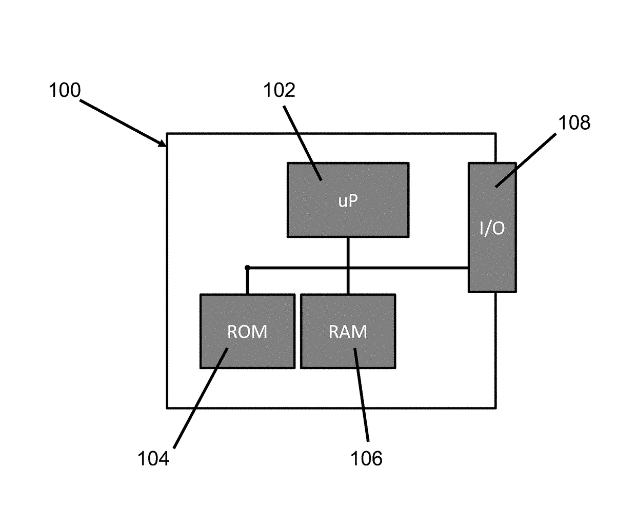
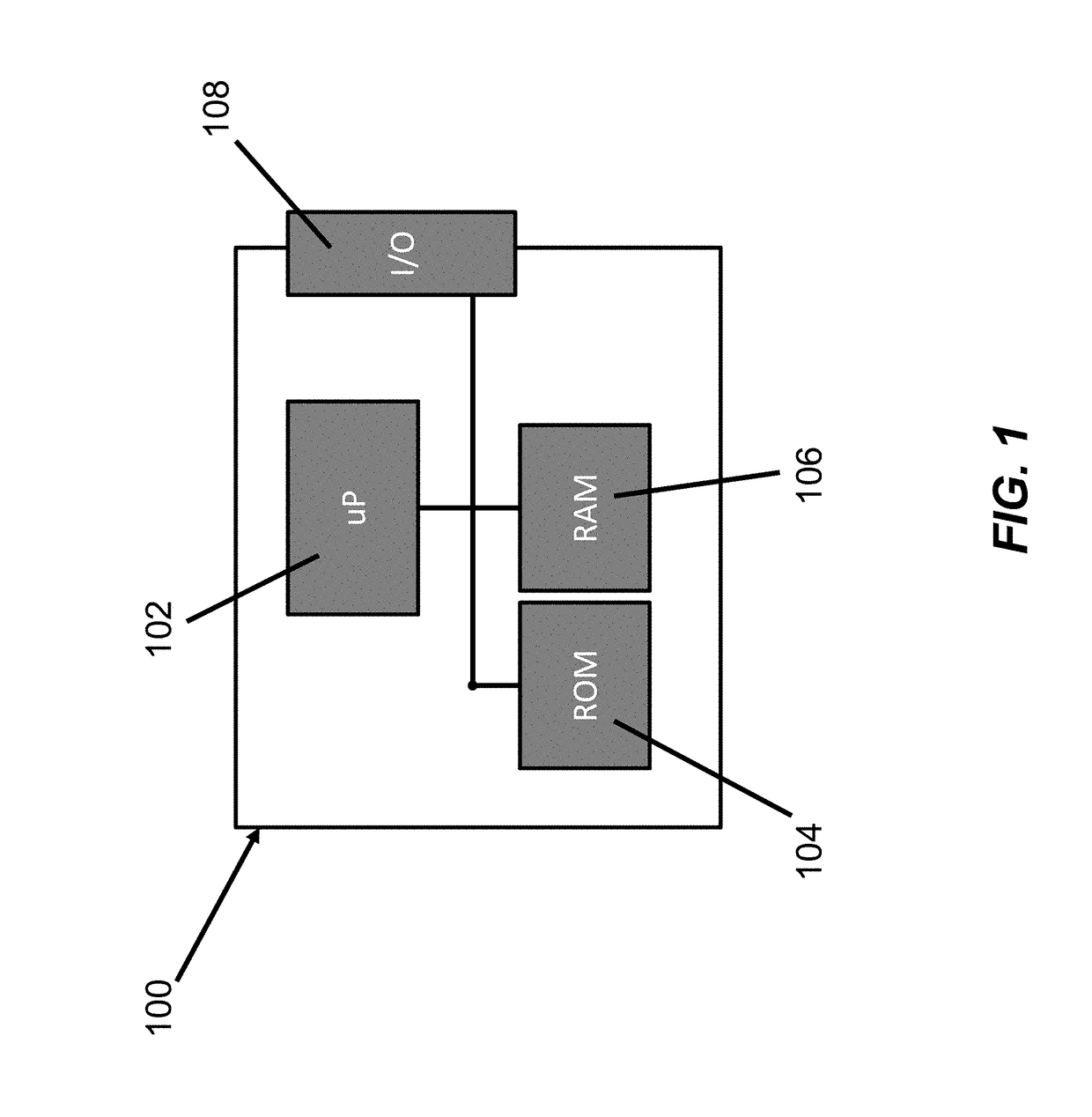
[0014]A basic diagram of a Vehicle Electronic Control Unit (ECU) is illustrated in FIG. 1. As is illustrated, a typical ECU 100 comprises a controller 102, and a memory further comprised of a read only memory (ROM) 104 for storing operating instructions and setpoints. Memory may also comprise random access memory (RAM) 106 which the controller ...


PUM


Abstract

The present invention is a system and method of making setpoint adjustments to a vehicle control computer in a real time manner in order to enable the one performing the programming to observe the changes in vehicle characteristics in real time. The system and method is an improvement over known methods in that it does not require the programmer to repeatedly stop and start the operation of the vehicle in order to verify that any changes have the desired result.

Description

TECHNICAL FIELD[0001]Exemplary embodiments of the present invention relate generally to a system and method for adjusting the performance of an automobile by changing various setpoints used by an automotive electronic control module to manage certain characteristics of an automobile.BACKGROUND AND SUMMARY OF THE INVENTION[0002]Modern automobiles may utilize computerized control systems to operate the various systems that comprise the automobile. These computerized systems have replaced the mechanical controllers that have been used in the past to control these systems. Generally referred to as Vehicle Electronic Control Units (ECU's), such controllers are able to manage the systems of an automobile much more efficiently than the mechanical devices used in the past. As a result, current automobiles are generally much more efficient and drivable than they were previously. ECU's are essentially dedicated computers that utilize setpoints and control curves to regulate vehicle systems. D...

Claims


Application Information

Patent Timeline
30 Nov 2017
Publication
US20170341603A1
IPC
B60R16/023; G06F9/44; G06F12/1009
CPC
B60R16/023; G06F2212/65; G06F12/1009; G06F9/4411; G01C25/00; G06F9/44505
Inventors
MILLIKEN, TIMOTHY G.