Asymmetric cam transmission

Active Publication Date: 2017-11-30
ONEILL JAMES L
View PDF12 Cites 5 Cited by
  • Summary
  • Abstract
  • Description
  • Claims
  • Application Information

AI Technical Summary

Benefits of technology

The present invention is a special type of transmission called a torque drive. It has two pairs of cams that rotate in opposite directions and are used to convert linear input into rotary output. Each cam has a unique angle that determines the direction in which it drives its shaft. This allows the cams to operate even when the input is starting from different positions. This design ensures that the cams and shafts rotate in opposite directions, regardless of the starting position, and makes it possible to achieve smooth and efficient operation of the transmission.

Problems solved by technology

Designers of power output devices, e.g., automobile, aircraft and locomotive engines / drive trains, are faced with a myriad of competing design criteria that result in various design compromises.
However, the Clerk is not twice as powerful as an Otto engine of the same displacement because of its lower efficiency per stroke.
From its brief description, it will be appreciated that the turbine engine is, perhaps, the most elegant, however, it too has disadvantages which limit its application.
This theoretical ratio is not realized in practice however because of the lower efficiency of the power stroke in a two-cycle engine.
Four-stroke engines, on the other hand, require a complex array of cam-driven valves for intake and exhaust.
Disadvantages of the two-stroke air-standard cycle generally involve wear, fuel efficiency and pollution.
The lack of a dedicated lubrication system typically results in a high rate of component wear.
Further, two-stroke reciprocating engines, which employ a conventional crankshaft, also experience accelerated wear of the piston.
Consequently, the piston rings wear, pressure is reduced i.e., causing blow-by, and fuel efficiency decreased.
Other disadvantages are simply due to the way fuel is burned (or not burned) in two-stroke engines.
Consequently, exhaust gases are intermixed with a fresh charge of air-gas, hence, the mixture for ignition is non-optimum, i.e., contaminated by exhaust gases from the previous stroke.
Consequently, two-stroke engines are not highly fuel efficient.
The disadvantages of four-stroke engines have been discussed above, i.e., when being compared to a two-stroke engine, however, suffice it to say that four-stroke engines deliver significantly less power output than two-stroke engines of the same displacement.
It will be appreciated that such devices add significant weight, require periodic maintenance, and are costly to fabricate, operate and maintain.
Other disadvantages of ICEs of the prior art relate to the weight distribution of conventional designs and to a lack of balanced torque output.
As such, this drive-train configuration is non-optimal in terms of weight and is highly mechanically complex.
As such these devices, which include tail cone structures, tail drive shafts, tail rotor gearboxes also add unnecessary weight.
As such, the torque imparted to each of the counter-rotating drive shafts is balanced resulting in cancellation of the reaction torque normally carried by the engine case.
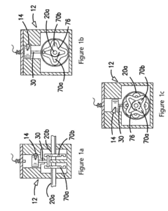
The ability of the lobed-cam to drive torque in opposite directions facilitates a number of useful applications, however, one difficulty that can arise relates to the inability to ensure counter-rotation of the cam plates.
That is, should the start-up or initial rotational position of the cams be such that the pistons are aligned with the top or bottom-dead center position within the cam profile, it may be impossible to initiate rotation of each in opposite directions without some external force or rotary drive input.


Method used


Image

  • Asymmetric cam transmission
  • Asymmetric cam transmission
  • Asymmetric cam transmission

Examples


Embodiment Construction

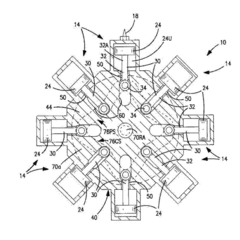
[0041]The present invention relates to a new and useful cam driven Internal Combustion Engine (ICE) that delivers high torque at low rotational velocity. The invention also describes a new and useful drive train operative to drive a pair of drive shafts in opposite directions.

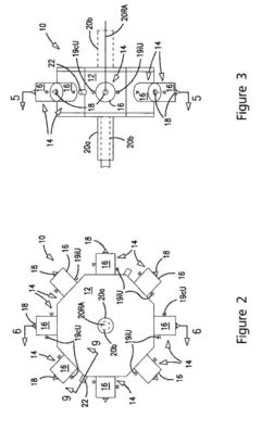
[0042]The preferred embodiment is described in the context of eight reciprocating pistons acting on two internal rotating drive cams that, in turn, drive coaxial output shafts. It will be appreciated, however, that the inventive features of the invention may be applied to similar internal combustion engines having fewer or a greater number of reciprocating pistons, to those having more than two cam drives, to those wherein the drive cams rotate in the same or opposite rotational directions, or to those having a single output drive shaft. The present invention also is directed to a torque drive transmission for driving an output relative to a rotating input. The output may be a reciprocating or rotating output w...


PUM


Abstract

A torque drive transmission, having at least two counter-rotating cams bearing-mounted within a housing about a rotational axis. The counter-rotating cams are operative to: (i) convert a linear input to a rotary output, and (ii) drive a pair of coaxial drive shafts in opposite directions along the rotational axis. Furthermore, each counter-rotating cam defines a cam profile surface having drive and follower surfaces defining angles α and β respectively. The angles α and β are unequal to drive each cam and respective output drive shaft in an opposite rotational direction. As such, the cams may be driven in opposite directions irrespective the initial rotational position of the linear input, i.e., relative to each counter-rotating cam.

Description

TECHNICAL FIELD[0001]This invention is directed to internal combustion engines / drive train systems, and more particularly, to internal combustion engines employing a torque drive transmission employing a drive cam converting linear motion of a piston / cylinder into rotational motion of an output drive shaft. The engine and drive train maximizes energy conversion, eliminates the need for intermediate speed reduction devices, improves performance, enhances reliability and reduces mechanical complexity.BACKGROUND[0002]Designers of power output devices, e.g., automobile, aircraft and locomotive engines / drive trains, are faced with a myriad of competing design criteria that result in various design compromises. For example, to optimize power output, a compromise in engine torque is often necessary. Similarly, when optimal energy conversion is desired, e.g., specific fuel consumption, a designer must choose an appropriate air-standard combustion cycle to match the requirement. In yet other...

Claims


Application Information

Patent Timeline
IPC IPC(8): F02B75/32F16H25/14F16H53/02F16H53/06
CPCF02B75/32F16H53/06F16H53/02F16H25/14F01B9/06F16H21/36F16H21/28
InventorO'NEILL, JAMES L.
OwnerONEILL JAMES L