Air pressure sensing system and air pressure sensing method

a sensing system and air pressure technology, applied in the direction of instruments, measurement devices, electrical equipment, etc., can solve the problems of the air pressure sensing system cannot accurately sense the pressure corresponding to the environment, and the output saturation or even damage of the diaphragm, etc., to achieve the effect of expanding the application range and improving the accuracy of air pressure sensing

Active Publication Date: 2017-11-30
MERRY ELECTRONICS SUZHOU
View PDF7 Cites 1 Cited by
  • Summary
  • Abstract
  • Description
  • Claims
  • Application Information

AI Technical Summary

Benefits of technology

[0005]The disclosure is directed to an air pressure sensing system and an air pressure sensing method, based on a composite pressure sensing structure and an intermittent sensing method, accuracy in air pressure sensing is effectively improved and an application range thereof is expanded.

Problems solved by technology

However, usage environments of the aforementioned products are diversified, and regarding an air pressure sensing system of a single type, when it is used in an environment with a larger difference in pressure, which is limited by a sensing range or a sensing accuracy of the air pressure sensing system, the air pressure sensing system cannot accurately sense a pressure corresponding to the environment or is probably failed due to excessive pressure variation.
However, when the pressure sensor is used in an environment with a larger pressure variation, for example, in an aircraft, since the pressure variation is too large within a short time, it may cause overload deformation of the diaphragm to result in output saturation or even damage of the diaphragm.
Therefore, how to achieve a larger pressure sensing range and a higher sensing accuracy of the pressure gauge simultaneously to improve applicability of the pressure gauge becomes an important issue to be studied by related technicians.

Method used


Image

  • Air pressure sensing system and air pressure sensing method
  • Air pressure sensing system and air pressure sensing method
  • Air pressure sensing system and air pressure sensing method

Examples


Embodiment Construction

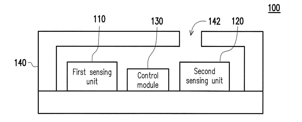
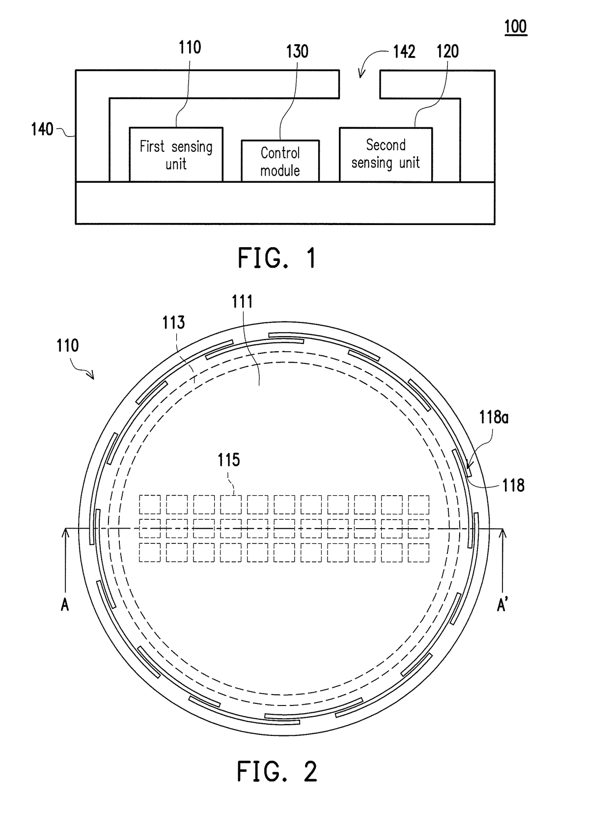
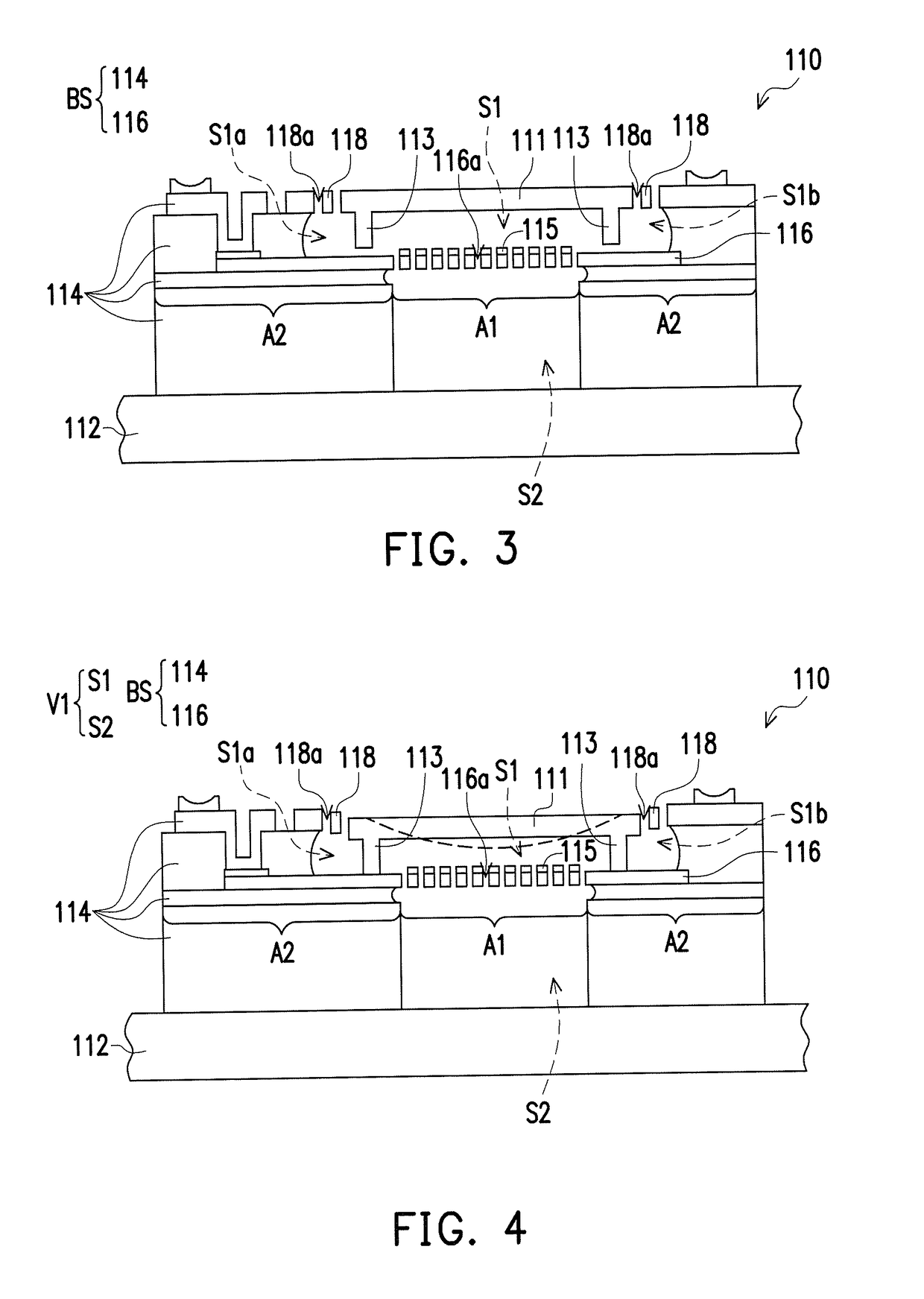
[0033]FIG. 1 is a schematic diagram of an air pressure sensing system according to an embodiment of the disclosure. FIG. 2 is a top view of a first sensing unit of the air pressure sensing system of FIG. 1. FIG. 3 and FIG. 4 are cross-sectional views of the first sensing unit in different states viewing along a section line A-A′ of FIG. 2. Referring to FIG. 1, in the present embodiment, the air pressure sensing system 100 includes a housing 140 and a first sensing unit 110, a second sensing unit 120 and a control module 130 disposed in the housing 140, where the control module 130 includes an application-specific integrated circuit (ASIC) or other functional module composed of components with the similar function, and the control module 130 is electrically connected with the first sensing unit 110 and the second sensing unit 120. The first sensing unit 110 is, for example, a capacitive pressure sensor manufactured based on micro electro mechanical system (MEMS) technology, and the s...


PUM

PropertyMeasurementUnit
electrostatic forceaaaaaaaaaa
elastic restoring forceaaaaaaaaaa
air pressureaaaaaaaaaa

Abstract

An air pressure sensing system including a first sensing unit and a second sensing unit is provided. The first sensing unit includes a substrate, a diaphragm, and a supporting member. The substrate has a cavity connected with an exterior environment. The diaphragm is movably and deformably disposed at the substrate and suspended in the cavity. An electrostatic force is provided to the substrate and the diaphragm to move the diaphragm, such that a portion of the base, the supporting member and the diaphragm are contacted with each other and a closed space is formed therebetween in the cavity. The closed space and the exterior environment are divided by the diaphragm, and the diaphragm is deformed due to an air pressure difference between the closed space and the exterior environment. An air pressure sensing method is also provided.

Description

CROSS-REFERENCE TO RELATED APPLICATIONS[0001]This application claims the priority benefit of Taiwan Patent Application No. 105116583, filed on May 27, 2016. The entirety of the above-mentioned patent application is hereby incorporated by reference herein and made a part of this specification.BACKGROUNDTechnical Field[0002]The disclosure relates to an air pressure sensing system and an air pressure sensing method.Description of Related Art[0003]Micro pressure sensor manufactured based on micro electro mechanical system (MEMS) technology have been widely used in consumer electronic products, vehicle electronic products, medical electronic products, industrial electronic products, etc. However, usage environments of the aforementioned products are diversified, and regarding an air pressure sensing system of a single type, when it is used in an environment with a larger difference in pressure, which is limited by a sensing range or a sensing accuracy of the air pressure sensing system, ...

Claims


Application Information

Patent Timeline
Patent Type & Authority Applications(United States)
IPC IPC(8): G01L13/02G01L19/00
CPCG01L19/0007G01L13/025G01L9/0054G01L9/0073G01L15/00G01L19/143H05K999/99
Inventor CHEN, JEN-YIWANG, CHUN-CHIEHCHANG, CHAO-SENCHANG, YUNG-SHIANG
Owner MERRY ELECTRONICS SUZHOU
Why Eureka
Try Eureka