Light source apparatus and projector
- Summary
- Abstract
- Description
- Claims
- Application Information
AI Technical Summary
Benefits of technology
Problems solved by technology
Method used
Image

Examples
first embodiment
Variation of First Embodiment
[0130]A variation of the first embodiment will be described below with reference to FIGS. 7 and 8.
[0131]The basic configuration of the illuminator of the present variation is the same as that in the first embodiment, but the configuration of the first light source unit of the first light source apparatus differs from that in the first embodiment. The overall first light source apparatus will therefore not be described, and only the first light source unit will be described.
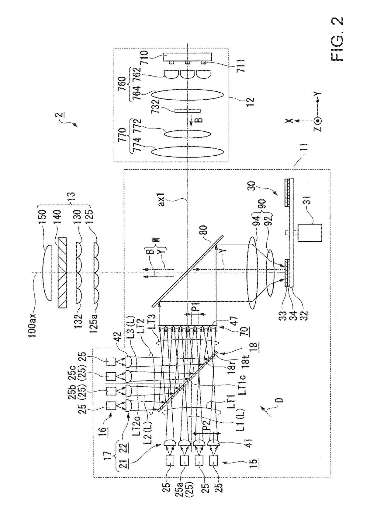
[0132]FIG. 7 is a plan view of the illuminator of the variation of the first embodiment. FIG. 8 is an enlarged view of key parts in FIG. 7.
[0133]In FIGS. 7 and 8, the same components as those in the drawings used in the first embodiment have the same reference characters and will not be described.
[0134]In a first light source apparatus 51 of the present variation, a first light source unit 52 includes the plurality of light emitting devices 25 including the first light emitting device ...
second embodiment
[0142]A second embodiment of the invention will be described below with reference to FIGS. 9 and 10.
[0143]The basic configuration of the light source apparatus of the second embodiment is the same as that in the first embodiment, but the configuration of the light beam conversion system differs from that in the first embodiment. The overall light source apparatus will therefore not be described, and only the light beam conversion system will be described.
[0144]FIG. 9 is a plan view of an illuminator of the second embodiment. FIG. 10 is a side view of the light emitting devices and the light beam conversion system.
[0145]In FIGS. 9 and 10, the same components as those in the drawings used in the first embodiment have the same reference characters and will not be described.
[0146]Also in the second embodiment, a first light source apparatus 61 corresponds to the light source apparatus in the appended claims, as in the first embodiment.
[0147]A light beam conversion system 62 provided in ...
third embodiment
[0154]A third embodiment of the invention will be described below with reference to FIG. 11.
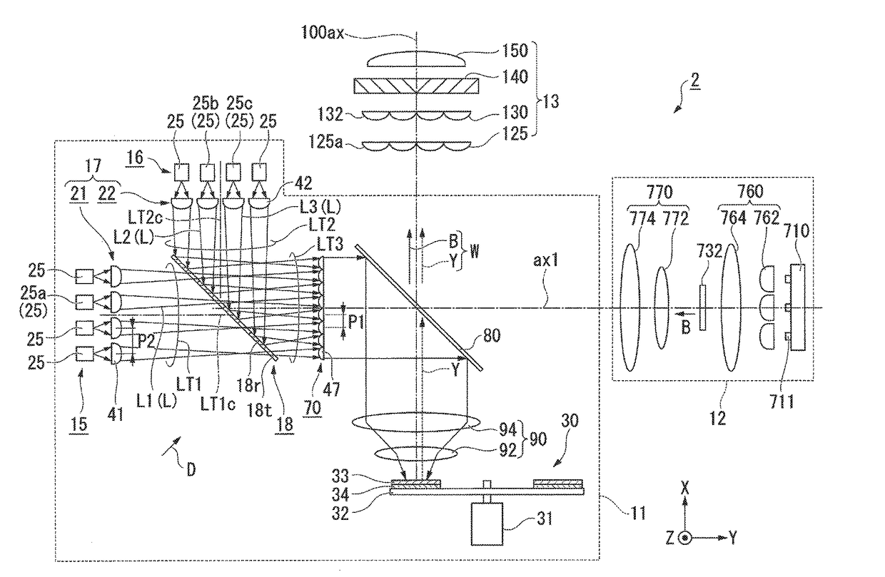
[0155]FIG. 11 is a plan view of key parts of the first light source apparatus of the third embodiment.
[0156]The basic configuration of the first light source apparatus of the third embodiment is the same as that in the first embodiment, but the configurations of the members downstream of the first collimation system differ from those in the first embodiment. The same portions as those in the first embodiment will therefore not be illustrated in FIG. 11.
[0157]In FIG. 11, the same components as those in FIG. 2 used in the first embodiment have the same reference characters and will not be described.
[0158]A first light source apparatus 101 of the third embodiment includes the light source unit 15, the second light source unit 16, the first light beam conversion system 17, the first light ray combiner 18, the first collimation system 70, a third light source unit 102, a fourth light source unit 1...
PUM
 Abstract
Description
Claims
Application Information
 - Generate Ideas
- Intellectual Property
- Life Sciences
- Materials
- Tech Scout
- Unparalleled Data Quality
- Higher Quality Content
- 60% Fewer Hallucinations
Browse by: Latest US Patents, China's latest patents, Technical Efficacy Thesaurus, Application Domain, Technology Topic, Popular Technical Reports.
© 2025 PatSnap. All rights reserved.Legal|Privacy policy|Modern Slavery Act Transparency Statement|Sitemap|About US| Contact US: help@patsnap.com