Control of long-stator linear motor coils of long-stator linear motor stator

a technology of linear motor and stator, which is applied in the direction of linear motor control, multiple ac dynamo-electric motor control, electric variable regulation, etc., can solve the problems of high circuit complexity and high cos

Active Publication Date: 2017-11-30
B&R IND AUTOMATION GMBH
View PDF11 Cites 4 Cited by
  • Summary
  • Abstract
  • Description
  • Claims
  • Application Information

AI Technical Summary

Benefits of technology

[0015]If the actual current is applied in m>1 phases, it is also possible to switch off the m phase currents, partially or entirely, in a manner dependent on the differential current. Thus, for example, a discontinuous drive is feasible. If the both the differential current and the potential difference are zero, then all of the phases may be deactivated,

Problems solved by technology

A naturally high number of LLM coils of an LLM stator thus entails hig

Method used


Image

  • Control of long-stator linear motor coils of long-stator linear motor stator
  • Control of long-stator linear motor coils of long-stator linear motor stator
  • Control of long-stator linear motor coils of long-stator linear motor stator

Examples


Embodiment Construction

[0005]The present invention addresses the problem of providing a method and device for controlling the LLM coils of an LLM stator that can be implemented more easily and with less circuit complexity and wherein the polarity of the coil voltage of the LLM coils also should be changeable.

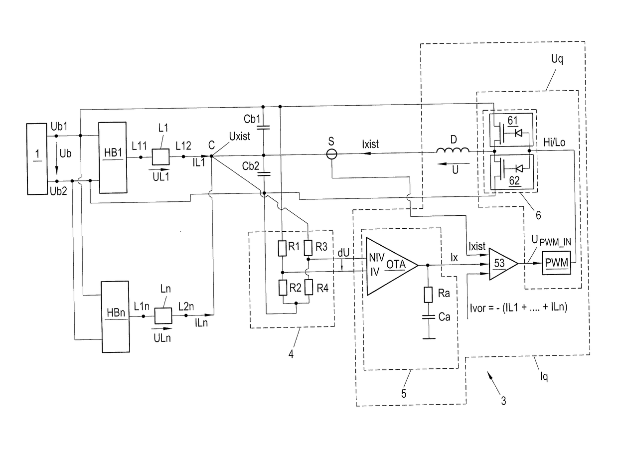
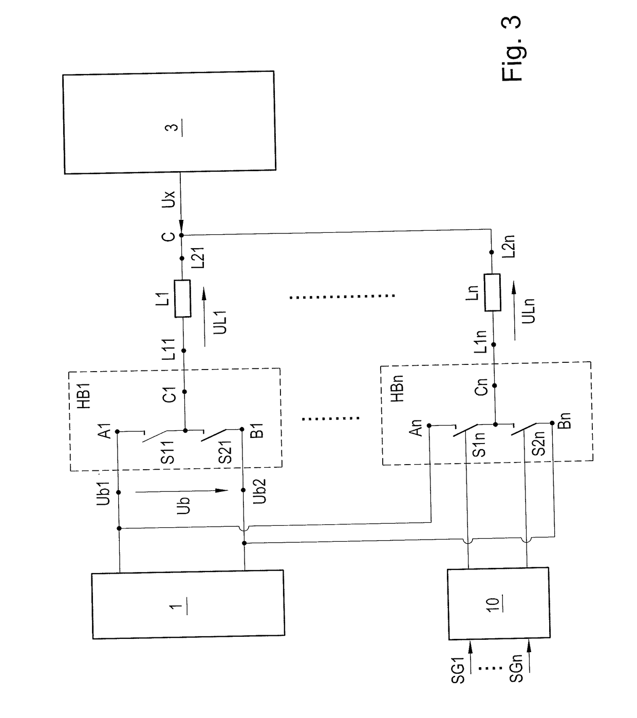
[0006]This problem is solved according to the present invention by: applying a first operating potential to the n first input terminals of n half bridges, applying a second operating potential to the n second input terminals of the n half bridges, and—per half bridge—connecting a first switch between a center point of the respective half bridge and the first input terminal, and connecting a second switch between the center point of the relevant half bridge and the second input terminal. The center point of the n half bridges is, in each case, connected to n first terminals of the n LLM coils. The second terminals of the n LLM coils are connected to a control point, and a control unit regulates an actu...


PUM


Abstract

The present invention provides a method and device for controlling the n LLM coils (L1, . . . Ln) of an LLM stator making it possible to change the polarity of the coil voltage (UL1, . . . , ULn) of the n LLM coils (L1, . . . Ln) more easily and with little circuit complexity. It is proposed to apply a first operating potential (Ub1) to n first input terminals (A1, . . . , An) of n half bridges (HB1, . . . , HBn), and apply a second operating potential (Ub2) to n second input terminals (B1, . . . , Bn) of the n half bridges. For each half bridge (HB1, . . . HBn), a first switch (S11, . . . , S1n) is connected between a center point (C1, . . . , Cn) of the respective half bridge (HB1, . . . , HBn) and the first input terminal (A1, . . . , An), and a second switch (S21, . . . , S2n) is connected between the center point (C1, . . . , Cn) of the relevant half bridge (HB1, . . . , HBn) and the second input terminal (B1, . . . , Bn). The center point (C1, . . . , Cn) of the n half bridges is connected in each case to n first terminals (L11, . . . , L1n) of the n LLM coils (L1, . . . , Ln), and the second terminals (L11, . . . , L1n) of the n LLM coils (L1, . . . , Ln) are connected in a control point (C) that is regulated to a predetermined potential (Ux).

Description

CROSS-REFERENCE TO RELATED APPLICATIONS[0001]The present application claims priority under 35 U.S.C. §119(a) of Austria Patent Application No. A50476 / 2016 filed May 25, 2016, the disclosure of which is expressly incorporated by reference herein in its entirety.BACKGROUND OF THE INVENTION1. Field of the Invention[0002]The present invention relates to a method and device for controlling a plurality of LLM coils of an LLM stator.2. Discussion of Background Information[0003]A stator of a long-stator linear motor (LLM) is composed of a plurality of adjacently-arranged LLM coils, which together form the stator of the LLM. These LLM coils are controlled individually or in groups, wherein, when the long-stator linear motor is running, it is often also desired or necessary to change the polarity, i.e., the direction of flow of the LLM coils. The control of the LLM coils produces a moving magnetic field that interacts with excitation magnets (usually permanent magnets) at a transport unit of ...

Claims


Application Information

Patent Timeline
IPC IPC(8): H02P25/064H02P6/00
CPCH02P6/006H02P25/064H02P6/28H02P7/02H02M3/156H02P7/292H02M7/219G05F1/575H02P25/06H02P5/74H02M1/0043
Inventor FASCHANG, LEOPOLDKLAPPAUF, CHRISTOF
Owner B&R IND AUTOMATION GMBH
Why Eureka
Try Eureka