Integrated environmental control for electronic equipment enclosures

a technology of environmental control and electronic equipment, applied in the direction of electrical equipment construction details, magnetic separation, chemistry apparatus and processes, etc., can solve the problems of affecting the performance, reliability, and lifespan of equipment, and the installation and operation of environmental control systems can be costly and laborious

Active Publication Date: 2017-11-30
ORACLE INT CORP
View PDF2 Cites 36 Cited by
  • Summary
  • Abstract
  • Description
  • Claims
  • Application Information

AI Technical Summary

Benefits of technology

[0003]Among other things, embodiments provide novel systems and methods for integrated control of environmental conditions in an equipment enclosure. For example, a novel airflow inlet structure can be installed into a primary airflow path of the equipment enclosure, the airflow inlet structure having an integrated electrostatic filter sub-structure and an integrated electromagnetic radiation (EMR) control sub-structure. The airflow inlet structure can be installed into a wall panel of the equipment enclosure. During operation of equipment within the enclosure, air drawn through the equipment enclosure can flow through the primary airflow path in such a way as to flow through the electrostatic filter sub-structure; and the EMR control sub-structure can control EMR emitted by the equipment, such that EMR leaving the enclosure is attenuated to below a threshold level.

Problems solved by technology

Traditionally, data centers have been located in highly controlled spaces because the equipment can be highly sensitive to environmental conditions.
Such environmental control systems can be costly to install and operate.
However, failing to have such environmental controls can cause particle buildup inside electronics equipment, which can negatively affect performance, reliability, and lifespan of the equipment.
Without filtering the air by a building HVAC system and / or CRACs, dust and other particulates can be drawn onto and into the equipment (e.g., tape / hard drive heads, heatsinks, switches, optical sensors), which can cause failures.

Method used


Image

  • Integrated environmental control for electronic equipment enclosures
  • Integrated environmental control for electronic equipment enclosures
  • Integrated environmental control for electronic equipment enclosures

Examples


Embodiment Construction

[0014]In the following description, numerous specific details are set forth to provide a thorough understanding of the present invention. However, one having ordinary skill in the art should recognize that the invention may be practiced without these specific details. In some instances, structures, and techniques have not been shown in detail to avoid obscuring the present invention.

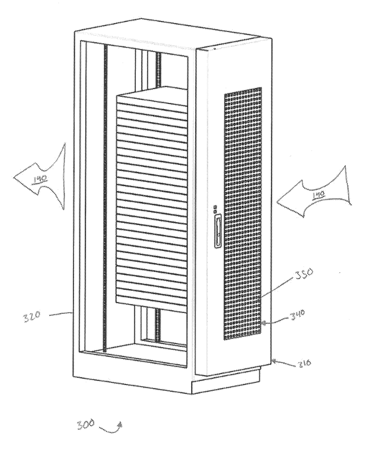
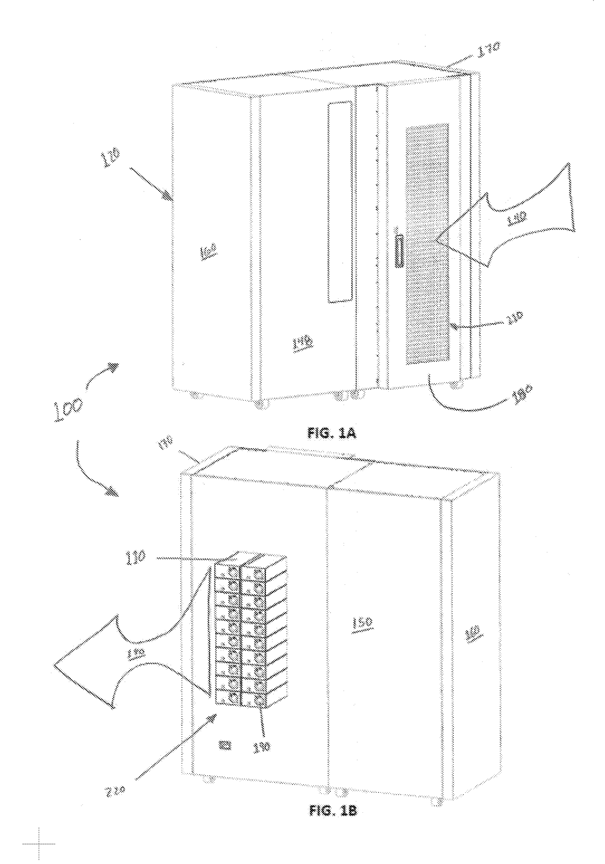
[0015]Turning first to FIGS. 1A and 1B, an illustrative electronic component system 100 is shown disposed in an enclosure, according to various embodiments. The electronic component system 100 is shown as a type of data storage library having multiple storage media and media drives. While a data storage library system is shown, embodiments described herein can apply in context of any suitable electronic system disposed in an enclosure, including, but not limited to, any suitable type of data storage library system. The illustrated data storage library system includes a number of storage media (not shown)...


PUM


Abstract

Embodiments include systems and methods for integrated control of environmental conditions in an equipment enclosure. For example, a novel airflow inlet structure can be installed into a primary airflow path of the equipment enclosure. The airflow inlet structure can include an integrated electrostatic filter sub-structure and an integrated electromagnetic radiation (EMR) control sub-structure. During operation of equipment within the enclosure, air drawn through the equipment enclosure can flow through the primary airflow path in such a way as to flow through the electrostatic filter sub-structure; and the EMR control sub-structure can control EMR emitted by the equipment, such that EMR leaving the enclosure is attenuated to below a threshold level.

Description

FIELD[0001]Embodiments relate generally to equipment enclosure environments, and, more particularly, to techniques for integrating environmental control in electronic equipment enclosure environments.BACKGROUND[0002]Traditionally, data centers have been located in highly controlled spaces because the equipment can be highly sensitive to environmental conditions. For example, such environments typically include systems for controlling temperature, humidity, air quality, etc. Typically, air in such environments is conditioned (e.g., filtered) by a central building heating, ventilating, and air conditioning (HVAC) system and / or by CRACs (Computer Room Air Conditioning units) in the data center. Such environmental control systems can be costly to install and operate. In some cases, operation of environmental controls can be a primary cost driver of a data center operation. However, failing to have such environmental controls can cause particle buildup inside electronics equipment, which...

Claims


Application Information

Patent Timeline
Patent Type & Authority Applications(United States)
IPC IPC(8): H05K7/20B03C3/82B03C3/02H05K9/00B03C3/017
CPCH05K7/20736H05K9/0041B03C3/82B03C3/017B03C3/02B03C3/41B03C3/47B03C2201/28
Inventor SMITH, FRANK
Owner ORACLE INT CORP
Why Eureka
Try Eureka