
Method for modifying surface of composite material, method for bonding composite material, composite material, and bonded structure

Active Publication Date: 2017-12-07
NISSAN MOTOR CO LTD
View PDF6 Cites 0 Cited by
  • Summary
  • Abstract
  • Description
  • Claims
  • Application Information

AI Technical Summary

Benefits of technology

The present invention provides a method for modifying the surface of a composite material to improve its bonding to a bonding agent while preventing deformation. This is achieved by applying a bonding agent to the fluffed reinforcing base material of the composite material, followed by the use of a laser to irradiate the surface of the composite material. The resulting improved bonding is likely due to the anchor effect and an increase in the bonding area. The present invention also provides a composite material with improved bonding to a bonding agent while suppressing deformation and a bonded structure comprising the same.

Problems solved by technology

However, in the bonding method disclosed in Patent Document 1, since not only the bonding agent, but also the composite materials, are heated by dielectric heating, there is the possibility that the composite materials may be deformed.

Method used


Image

  • Method for modifying surface of composite material, method for bonding composite material, composite material, and bonded structure
  • Method for modifying surface of composite material, method for bonding composite material, composite material, and bonded structure
  • Method for modifying surface of composite material, method for bonding composite material, composite material, and bonded structure

Examples


Embodiment Construction

[0028]Embodiments of the present invention will be explained below, with reference to the appended drawings. In the explanations of the drawings, the same elements are given the same codes, and overlapping explanations are omitted. Dimensional ratios of the drawings are exaggerated for convenience of explanation and may be different from the actual ratio.

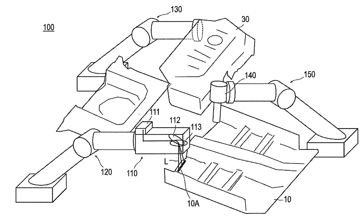
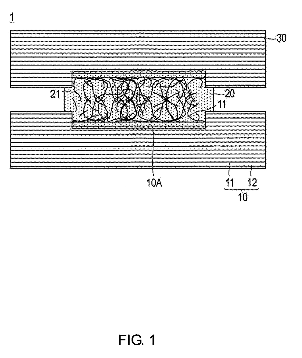
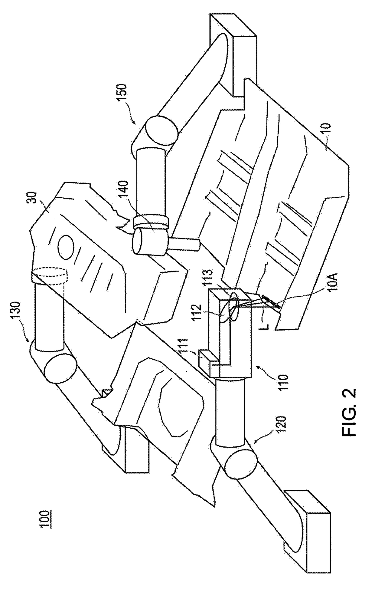
[0029]FIG. 1 is a schematic view illustrating the bonded structure 1 according to an embodiment of the present invention. FIG. 2 is a view illustrating the method for modifying the surface of a composite material 10 according to the present embodiment. FIG. 3 is a flowchart illustrating the method for bonding a composite material 10 according to the present embodiment. FIG. 4 is a schematic view illustrating a state in which a reinforcing base material 11 is exposed. FIG. 5 is a schematic view illustrating a state in which the reinforcing base material 11 is fluffed. FIG. 6 is a schematic view illustrating a state in which laser L i...


PUM

PropertyMeasurementUnit
Structureaaaaaaaaaa
Areaaaaaaaaaaa

Abstract

A composite material is formed by irradiating a bonding position on a surface of the composite material with a laser to cause a reinforcing base member of the composite material, that is impregnated with a resin and onto which a bonding agent is applied, to be exposed and fluffed.

Description

CROSS-REFERENCE TO RELATED APPLICATIONS[0001]This application is a U.S. National stage application of International Application No. PCT / JP2014 / 084677, filed Dec. 26, 2014.BACKGROUNDField of the Invention[0002]The present invention relates to a method for modifying the surface of a composite material; a method for bonding a composite material; a composite material; and a bonded structure.Background Information[0003]In recent years, composite materials made by impregnating a reinforcing base material with resin have been used as automobile parts to reduce the body weight of automobiles. Automobile parts are formed by joining composite materials to each other via a bonding agent, but in general, since bonding between composite materials and the bonding agent is low, it is necessary to improve the bonding of the composite material to the bonding agent.[0004]In relation to the foregoing, for example, Japanese Laid Open Patent Application No. 2013-166904 (Patent Document 1) below disclose...

Claims


Application Information

Patent Timeline
IPC IPC(8): B29B13/08B29C59/16B29C65/48B32B5/24
CPCB29B13/08B32B5/24B29C59/16B29C65/483B32B5/28B29C65/4835B29C65/4845B29C65/524B29C65/8207B29C66/0246B29C66/1122B29C66/21B29C66/30325B29C66/41B29C66/721B29C66/7212B29C66/7394B29C65/488B29C66/3034B29K2309/08B29K2307/04
Inventor HAMAGUCHI, YUJIFUKUMOTO, TAKAFUMIMOROHOSHI, KATSUMIUSUI, KATSUHIROTAKANO, AYAKO
Owner NISSAN MOTOR CO LTD
Features
  • Generate Ideas
  • Intellectual Property
  • Life Sciences
  • Materials
  • Tech Scout
  • Unparalleled Data Quality
  • Higher Quality Content
  • 60% Fewer Hallucinations
Learn More