Mono-rail crane system in an aircraft

a monorail crane and crane technology, applied in the field of monorail crane systems in aircraft, can solve the problems of cumbersome and expensive use of hoisting platforms, inability to implement conveyor belt solutions, and inability to meet the requirements of passenger safety, so as to minimize the lateral force and torque/torsion transmitted to the rail

Active Publication Date: 2017-12-07
AIRBUS DEFENCE & SPACE
View PDF0 Cites 10 Cited by
  • Summary
  • Abstract
  • Description
  • Claims
  • Application Information

AI Technical Summary

Benefits of technology

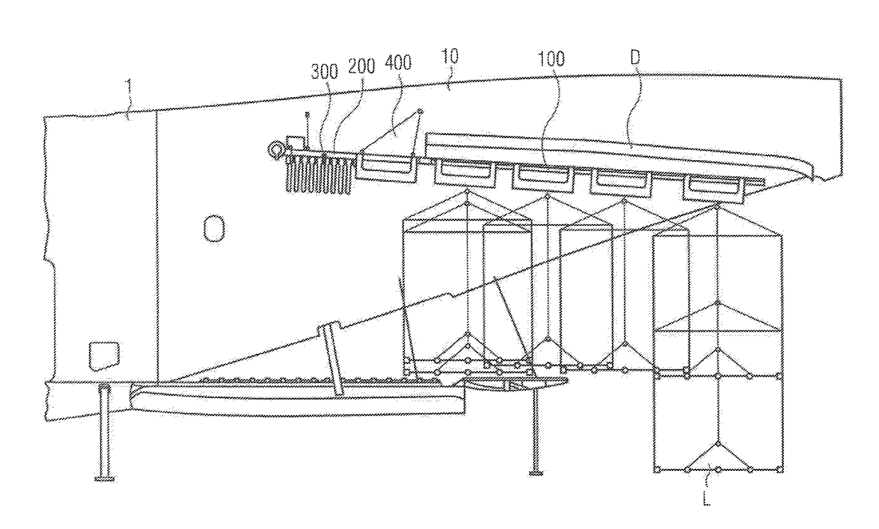
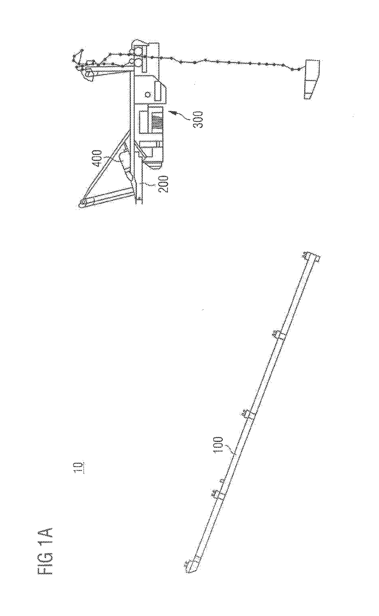
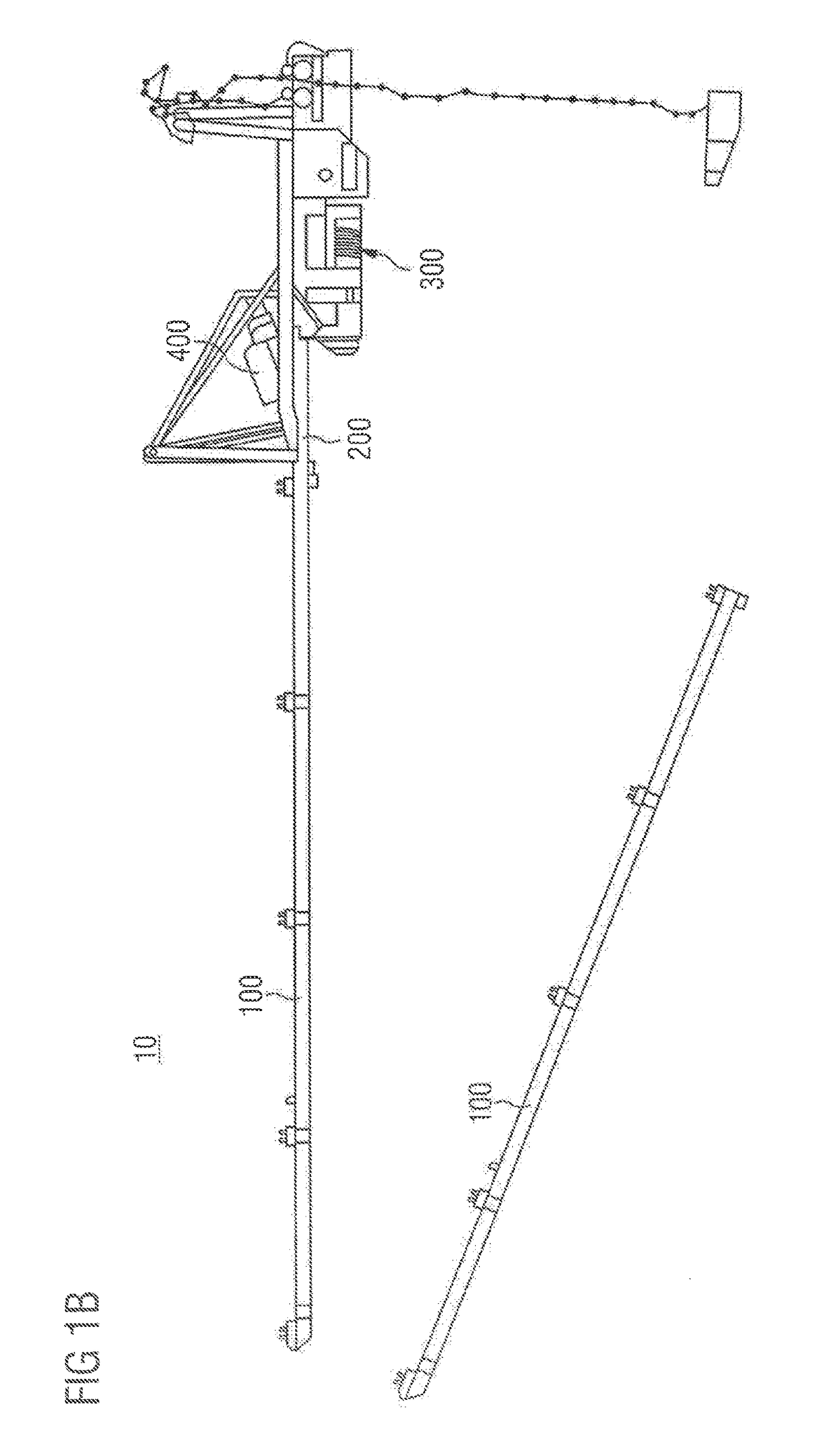
[0008]There is provided a mono-rail crane system for use in an aircraft, the crane system enabling the transfer of a load from outside the aircraft into the aircraft and vice versa, and comprising a first longitudinal mono-rail installable on the underside of a rear cargo door of the airplane parallel to the longitudinal axis of the rear cargo door; a second longitudinal mono-rail, which is installable on a cargo hold ceiling of the aircraft, and, in the fully opened state of the rear cargo door, in aligned continuity with the first longitudinal mono-rail so that the longitudinal axes of the first and second longitudinal mono-rails coincide to form one common longitudinal axis; a crane mobile equipment, CME, configured to be movable along the first and second longitudinal mono-rails in order to hoist and transfer the load; and a linear actuator configured to advance and retreat the second longitudinal monorail towards and away from the first longitudinal monorail. Such a system enables crane stowage so as not to protrude into the cargo hold envelope and will not interfere with opening / closing the rear cargo door.
[0009]In the fully opened state of the rear cargo door, the common longitudinal axis may be under a predetermined angle in relation to a horizontal plane of the aircraft, the horizontal plane containing the center line of the fuselage of the airplane. In this case, the predetermined angle may be 3.5° and may have a tolerance of + / −2.0°. Still further, the load may have weight of up to 5000 kg. In this way, intermediate weight loads can be handled efficiently.
[0011]The CME may be, during flight mode, secured in a stowage position at the proximal end of the second longitudinal monorail, and, during operational mode, able to move between the stowage position and the distal end of the first longitudinal mono-rail. If so, the first and second longitudinal mono-rails may each comprise a rolling surface for the CME. In the latter case, the rolling surfaces may be one of substantially flat and formed in the form of a toothed rack so as to engage with the CME. In addition or alternatively, the CME may further comprise a wheel mechanism so as to compensate for a displacement between the tracks and a further displacement at the transition between the first and second longitudinal mono-rails. In this way, the CME is implemented efficiently.
[0012]The CME may further comprise an attaching device configured to physically displace an arresting point between the CME and the load. Thus, lateral forces and torque / torsion transmitted to the rail are minimized.
[0014]The most proximal slide bracket of the first longitudinal mono-rail may be configured as a female locator housing, and a most distal bracket of the second longitudinal mono-rail may be configured as a male alignment device so as to establish the aligned continuity between the first and second longitudinal upon advancing movement of the linear actuator. In this way, when establishing the operation mode of the crane system, the system is easy-to-use.

Problems solved by technology

When it comes to transferring more heavy loads (such as loads equal to or greater than 2000 kg), the conveyor belt solution is no longer feasible.
However, such a hoisting platform is cumbersome and expensive to use and is also over-dimensioned for intermediate weight loads (e.g., between 2000 kg and 5000 kg).
The main problem with external cranes is, again, their cumbersome and expensive usage, while internal cranes are more favorable in this respect.
However, internal cranes are subject to numerous constraints, such as requirements by law for permitting the crane, and also constraints pertaining to opening / closing the rear cargo door of the aircraft.

Method used


Image

  • Mono-rail crane system in an aircraft
  • Mono-rail crane system in an aircraft
  • Mono-rail crane system in an aircraft

Examples


Embodiment Construction

[0049]In the following description, for purposes of explanation and not limitation, specific details are set forth (such as particular signaling steps) in order to provide a thorough understanding of the technique presented herein. It will be apparent to one skilled in the art that the present technique may be practiced in other embodiments that depart from these specific details.

[0050]Moreover, those skilled in the art will appreciate that the services, functions and steps explained herein may be implemented using software functioning in conjunction with a programmed microprocessor, or using an Application Specific Integrated Circuit (ASIC), a Digital Signal Processor (DSP) or general purpose computer. It will also be appreciated that while the following embodiments are described in the context of methods and devices, the technique presented herein may also be embodied in a computer program product as well as in a system comprising a computer processor and a memory coupled to the p...


PUM


Abstract

A mono-rail crane system (and a corresponding operation method) for use in an aircraft. The crane system comprises a first longitudinal mono-rail installable on the underside of a rear cargo door of the airplane parallel to the longitudinal axis of the rear cargo door; a second longitudinal mono-rail, which is installable on a cargo hold ceiling of the aircraft, and, in the fully opened state of the rear cargo door, in aligned continuity with the first longitudinal mono-rail so that the longitudinal axes of the first and second longitudinal mono-rails coincide to form one common longitudinal axis; a crane mobile equipment configured to be moved along the first and second longitudinal mono-rails in order to hoist and transfer the load; and a linear actuator configured to advance and retreat the second longitudinal monorail towards and away from the first longitudinal monorail.

Description

CROSS-REFERENCES TO RELATED APPLICATIONS[0001]This application claims the benefit of the European patent application No. 16 380 027.9 filed on Jun. 7, 2016, the entire disclosures of which are incorporated herein by way of reference.BACKGROUND OF THE INVENTION[0002]The present disclosure generally relates to a mono-rail crane system in an aircraft. In particular, the present disclosure relates to a mono-rail crane system in an aircraft enabling the transfer of loads from outside the aircraft into the aircraft, and the other way around.[0003]Transferring loads from / into the cargo bay of an aircraft is an integral part of air traffic nowadays. As far as lighter loads (such as suitcases) are involved, the classical inclined conveyor belt can be used.[0004]When it comes to transferring more heavy loads (such as loads equal to or greater than 2000 kg), the conveyor belt solution is no longer feasible. For extremely heavy loads (such as loads greater than 5000 kg), an external hoisting pl...

Claims


Application Information

Patent Timeline
Patent Type & Authority Applications(United States)
IPC IPC(8): B64C1/22B64F1/32B64D9/00B66C19/00
CPCB64C1/22B66C19/002B64D9/00B64F1/32B64C1/1415B64F1/322
Inventor LOPEZ, ANA RUBIOARIAS, DANIEL LLANESMARTINEZ, OSCARLOHMANN, ALIWEISS, ULRICH
Owner AIRBUS DEFENCE & SPACE
Why Eureka
Try Eureka