Exhaust purification device for engine

a technology for exhaust purification devices and engines, which is applied to engines, mechanical equipment, machines/engines, etc., can solve the problems of still taking a long time to thaw urea aqueous solution, and achieve the effect of shortening the thawing tim

Active Publication Date: 2017-12-07
NISSAN DIESEL MOTOR CO
View PDF6 Cites 3 Cited by
  • Summary
  • Abstract
  • Description
  • Claims
  • Application Information

AI Technical Summary

Benefits of technology

[0007]According to an aspect of the present invention, there is provided the structure in which the at least a part of the reducing agent or the precursor thereof to be supplied to the injection nozzle is heated and returned to the reducing agent tank, and accordingly, it is made possible to further shorten the thawing time.

Problems solved by technology

However, it has still taken a long time to thaw the urea aqueous solution even if the above-described countermeasures are taken, and a further improvement has been required.

Method used


Image

  • Exhaust purification device for engine
  • Exhaust purification device for engine
  • Exhaust purification device for engine

Examples


Embodiment Construction

[0016]Hereinafter, embodiments of the present invention will be described in detail.

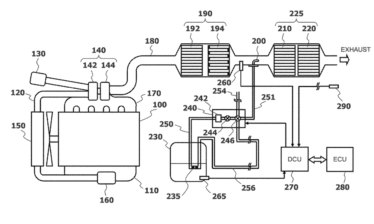
[0017]FIG. 1 illustrates an example of an exhaust purification device that purifies particulate matter (PM) and NOx in exhaust.

[0018]In an intake pipe 120 connected to an intake manifold 110 of a diesel engine 100, along an intake air flowing direction, there are disposed, in a following order: an air cleaner 130 that filters dust and the like in intake air; a compressor 142 of a turbocharger 140 that supercharges the intake air; an intercooler 150 that cools the intake air that has passed through the compressor 142; and an intake collector 160 that smoothes pulsation of the intake air.

[0019]Meanwhile, in an exhaust pipe 180 connected to an exhaust manifold 170 of the diesel engine 100, along an exhaust flowing direction, there are disposed, in a following order: a turbine 144 of the turbocharger 140; a continuous regeneration-type diesel particulate filter (hereinafter referred to as “DPF”) device 1...


PUM


Abstract

An exhaust purification device for an engine facilitates thawing of a urea aqueous solution, which is frozen in a reducing agent tank of an exhaust purification device, more rapidly. When a urea aqueous solution in a reducing agent tank is frozen at a time of starting an engine, at least a part of the urea aqueous solution to be supplied to an injection nozzle is flown into a reducing agent circulation flow path, a part of which is adjacent to a heat source, and the urea aqueous solution thus heated is returned to the reducing agent tank.

Description

BACKGROUND AND SUMMARY[0001]The present invention relates to an exhaust purification device for an engine, which selectively reduces and purifies nitrogen oxide (NOx) in exhaust by a reducing agent.[0002]In an exhaust system for an engine, an exhaust purification device is known, which includes: a selective reduction catalytic converter that selectively reduces and purifies NOx by using ammonia as a reducing agent; and an injection nozzle that injects a urea aqueous solution (a precursor thereof), the injection nozzle being provided upstream the selective reduction catalytic converter in a flow of the exhaust.[0003]Since the urea aqueous solution is frozen at approximately −11° C., there is known such a technology as described in Patent Document 1, in which, after an engine is stopped, a freezing change of the urea aqueous solution, which remains in the injection nozzle and a reducing agent supply flow path, is monitored, and in addition, the injection nozzle is temporarily opened f...

Claims


Application Information

Patent Timeline
Patent Type & Authority Applications(United States)
IPC IPC(8): F01N3/20F01N3/035F01N9/00F01N13/00F02B37/00
CPCF01N3/208F01N3/035F02B37/00F01N9/00F01N13/0097F01N3/2066F01N2240/02F01N2560/06F01N2610/02F01N2610/10F01N2610/1473F01N2610/1493F01N2900/1811Y02T10/12
Inventor TOMITA, YASUTOSHI
Owner NISSAN DIESEL MOTOR CO
Why Eureka
Try Eureka