Conversion process comprising at least one step for fixed bed hydrotreatment and a step for hydrocracking in by-passable reactors

a conversion process and hydrotreatment technology, applied in the field of refining and to the conversion of heavy hydrocarbon fractions, can solve the problem of degrading the quality of fuel oil by insufficient sediments, and achieve the effect of reducing the pressure drop of the reaction section

Active Publication Date: 2017-12-14
INST FR DU PETROLE
View PDF3 Cites 19 Cited by
  • Summary
  • Abstract
  • Description
  • Claims
  • Application Information

AI Technical Summary

Benefits of technology

[0021]During the period from the start to approximately the middle of the cycle, deactivation of the catalysts of the hydrotreatment section is low and the catalysts are thus active at moderate temperatures, which results in the production of very stable effluents which are free from sediments; thus, there is an interest in exploiting this margin of stability by applying a by-passable reactor hydrocrack...

Problems solved by technology

However, the temperatures sometimes reached from the middle of the cycle and up to the end of the cycle for fixed bed processes for the hydrotreatment of residues may lead to the formation of s...

Method used


Image

  • Conversion process comprising at least one step for fixed bed hydrotreatment and a step for hydrocracking in by-passable reactors
  • Conversion process comprising at least one step for fixed bed hydrotreatment and a step for hydrocracking in by-passable reactors
  • Conversion process comprising at least one step for fixed bed hydrotreatment and a step for hydrocracking in by-passable reactors

Examples


example

Example 1 (not in Accordance with the Invention)

[0092]The feed was a mixture of atmospheric residues (AR) of Middle Eastern origin. This mixture was characterized by a large quantity of metals (100 ppm by weight) and sulphur (4.0% by weight) as well as 7% of [370-].

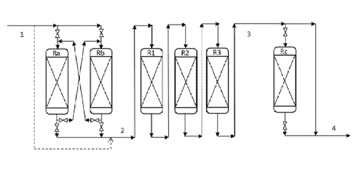
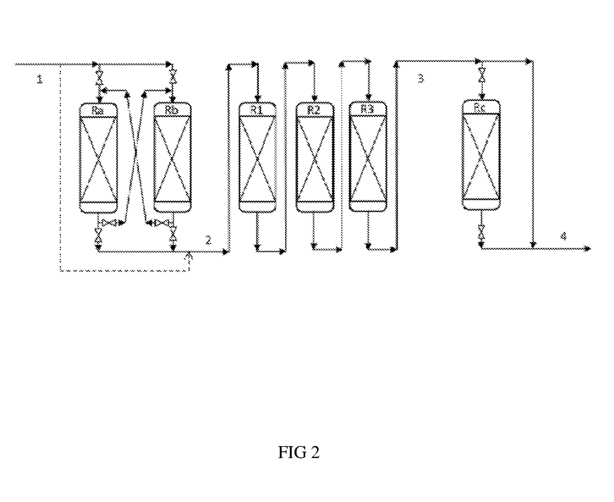
[0093]The hydrotreatment process comprised the use of three fixed bed reactors (R1, R2 and R3) with a downflow of liquid within which the steps termed hydrodemetallization (HDM) and hydrotreatment (HDT) were carried out.

[0094]The effluent obtained from these two steps was flash separated in order to obtain a liquid fraction and a gaseous fraction containing gases, in particular H2, H2S, NH3 and C1-C4 hydrocarbons. The liquid fraction was then stripped in a column then fractionated in an atmospheric column then a vacuum column into several cuts (IP-350° C., 350-520° C. and 520° C.+).

[0095]The reactor R1 was charged with hydrodemetallization catalyst and the reactors R2, R3 with hydrotreatment catalyst. The process was carr...

example 2 (

in Accordance with the Invention)

[0100]In this example, the process in accordance with the invention was operated with the same feed, the same catalysts and under the same operating conditions for the reactor R1. Reactor R2 was operated under the same operating conditions, but its HSV was higher.

[0101]The process in accordance with the invention involved the use of a novel by-passable hydrocracking reactor denoted Rc, replacing the reactor R3 which appeared in the hydrotreatment section (HDT) of the prior art. This hydrocracking step was carried out at high temperature downstream of the hydrodemetallization and fixed bed hydrotreatment steps which were carried out in the reactors R1 and R2.

[0102]Table 2 below provides an example of the operation of the by-passable reactor Rc.

TABLE 2Operations around the by-passable reactorin accordance with the inventionFixed bed reactorsBy-passable hydrocracking reactorSequencesHDM / TransitionHDTOff lineHCK1R1R2—Rc2R1R2Rc—

[0103]During sequence 1, th...


PUM


Abstract

The invention concerns a process for the treatment of a hydrocarbon feed in order to obtain a heavy hydrocarbon fraction with a low sulphur content, said process comprising the following steps: a) an optional step for hydrodemetallization carried out in permutable reactors, b) a step for fixed bed hydrotreatment of the effluent obtained from step a), c) a step for hydrocracking of the effluent obtained in step b) in by-passable reactors, d) a step for separation of the effluent obtained from step c).

Description

CONTEXT OF THE INVENTION[0001]The present invention relates to refining and to the conversion of heavy hydrocarbon fractions containing sulphur-containing impurities, inter alia. More particularly, it relates to a process for the conversion of heavy oil feeds of the atmospheric residue and / or vacuum residue type for the production of heavy fractions for use as fuel oil bases, in particular bunker fuel bases, with a low sediments content. The process in accordance with the invention can also be used to produce atmospheric distillates (naphtha, kerosene and diesel), vacuum distillates and light gases (C1 to C4).[0002]The quality requirements for marine fuels are described in ISO standard 8217. The specification concerning sulphur will from now on concern the emissions of SOx (Annexe VI of the MARPOL convention from the International Maritime Organisation). It is translated as a recommendation for a sulphur content of 0.5% by weight or less outside the Emission Control Areas (ECA) for ...

Claims


Application Information

Patent Timeline
IPC IPC(8): C10G67/02
CPCC10G67/02C10G2300/205C10G2300/202C10G7/06C10G45/08C10G47/12C10G65/04C10G65/12C10G2300/1077
Inventor WEISS, WILFRIEDTELLIER, ELODIECHATRON-MICHAUD, PASCAL
Owner INST FR DU PETROLE
Why Eureka
Try Eureka