System and method for operating an engine oil pump

a technology for oil pumps and engine oil, applied in mechanical equipment, machines/engines, electric control, etc., can solve the problems of engine fuel consumption depletion, engine lubrication may not be sufficient, engine devices may not operate as expected, etc., and achieve low engine fuel consumption and increase the output pressure of oil pumps

Active Publication Date: 2017-12-14
FORD GLOBAL TECH LLC
View PDF15 Cites 19 Cited by
  • Summary
  • Abstract
  • Description
  • Claims
  • Application Information

AI Technical Summary

Benefits of technology

[0003]Oil may be pumped throughout an engine to lubricate engine components. In addition, oil may be used in the engine as a motive power medium to actuate various devices within the engine. For example, an engine may include valve operators that may be selectively deactivated by supplying pressurized oil to the valve operators. The same engine may also include piston cooling jets that spray oil on engine pistons to cool the engine pistons. A variable displacement oil pump may pump oil throughout the engine and oil pump output pressure may be increased via in

Problems solved by technology

However, if the oil pump is operated at too high of a pressure, engine fuel consumption may degrade.
Conversely, if the oil pump is opera

Method used


Image

  • System and method for operating an engine oil pump
  • System and method for operating an engine oil pump
  • System and method for operating an engine oil pump

Examples


Embodiment Construction

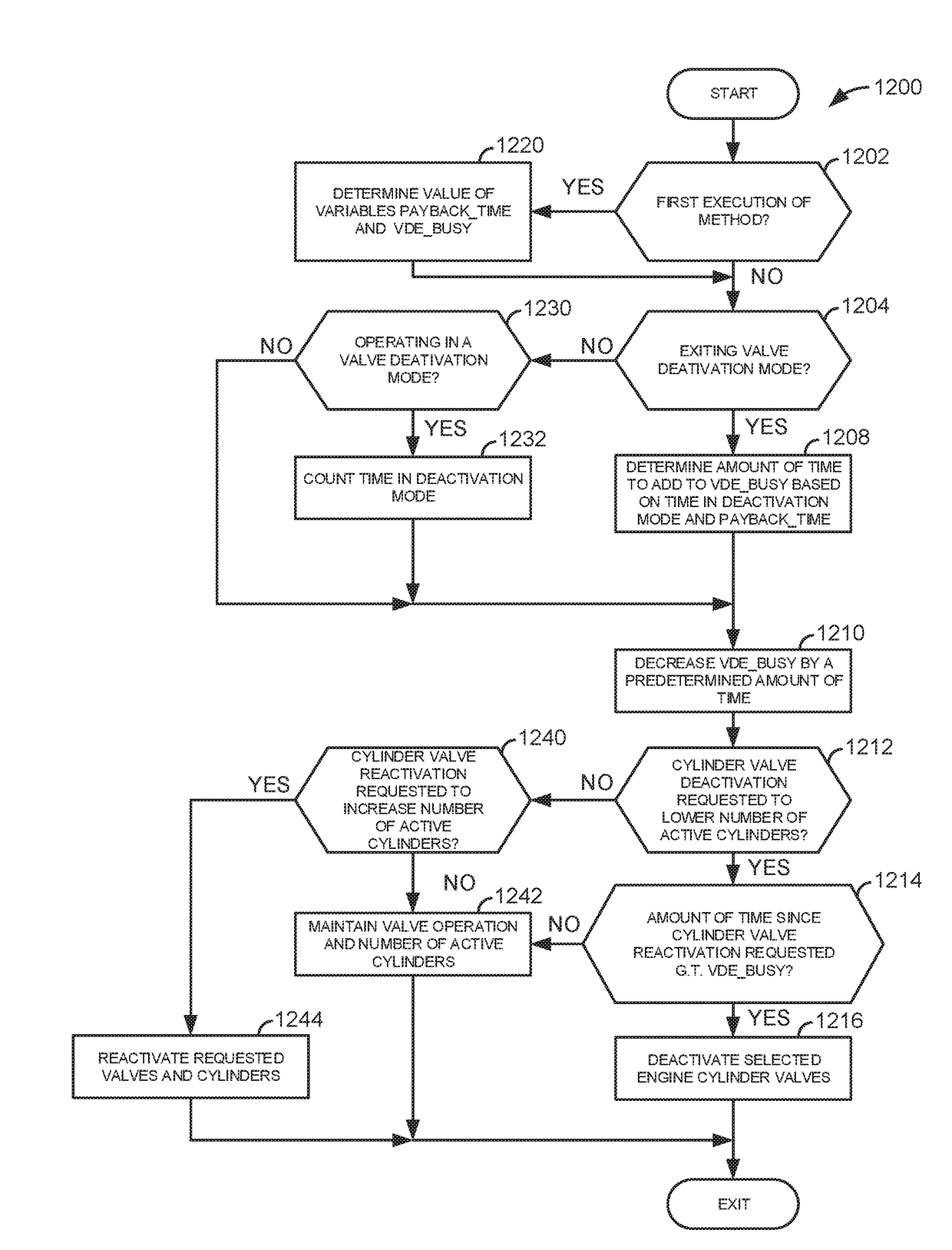
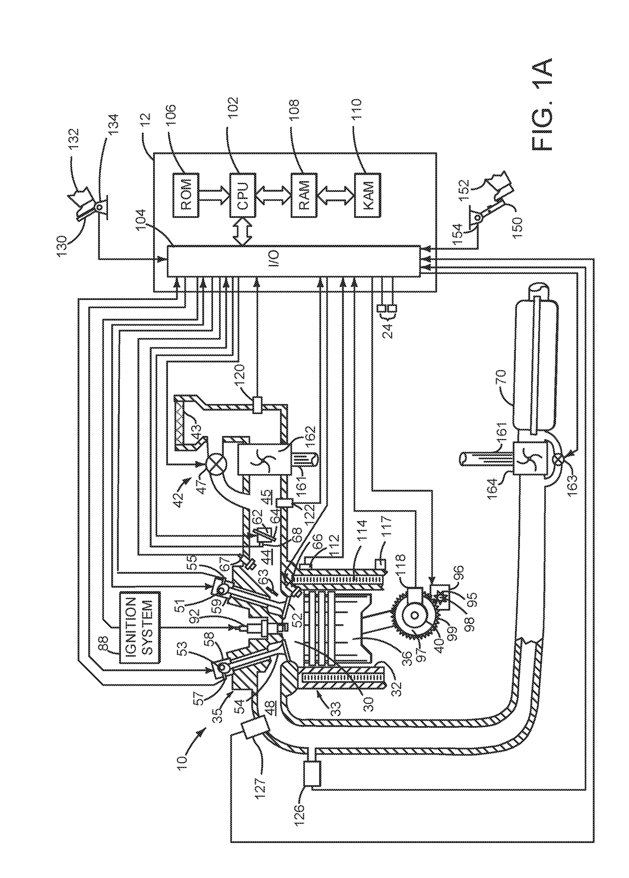
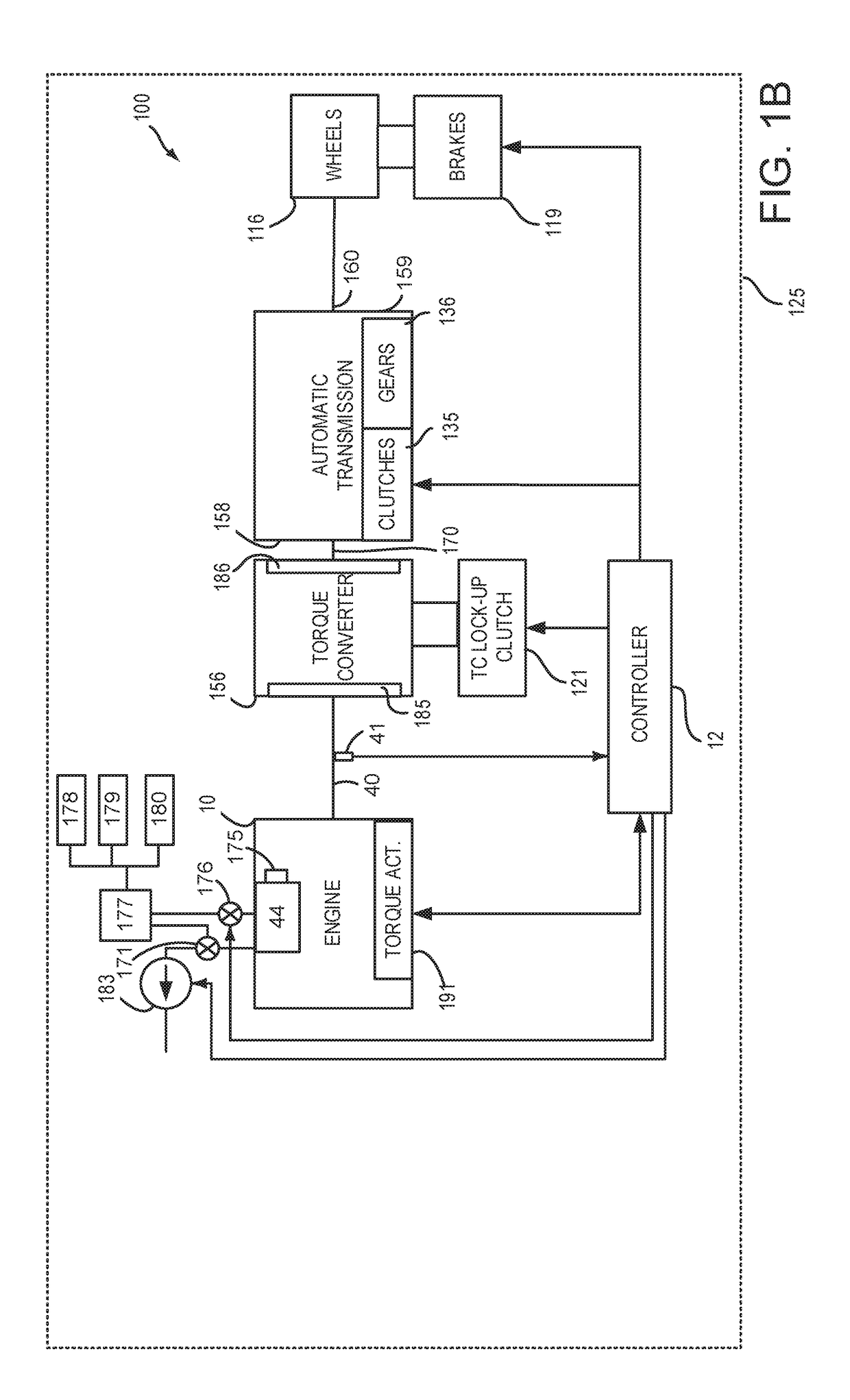
[0060]The present description is related to systems and methods for selectively activating and deactivating cylinders and cylinder valves of an internal combustion engine. The engine may be configured and operate as is shown in FIGS. 1A-6D. Various methods and prophetic operating sequences for an engine that includes deactivating valves are shown in FIGS. 7-42. The different methods may operate cooperatively and with the systems shown in FIGS. 1A-6D.

[0061]Referring to FIG. 1A, internal combustion engine 10, comprising a plurality of cylinders, one cylinder of which is shown in FIG. 1A, is controlled by electronic engine controller 12. Engine 10 is comprised of cylinder head casting 35 and block 33, which include combustion chamber 30 and cylinder walls 32. Piston 36 is positioned therein and reciprocates via a connection to crankshaft 40. Flywheel 97 and ring gear 99 are coupled to crankshaft 40. Starter 96 (e.g., low voltage (operated with less than 30 volts) electric machine) incl...


PUM


Abstract

Systems and methods for operating an engine with an oil pump that supplies engine oil to various oil consumers in an engine are presented. In one example, a displacement of a variable displacement engine oil pump is adjusted to provide sufficient oil pressure throughout the engine, but low enough to conserve fuel.

Description

CROSS REFERENCE TO RELATED APPLICATION[0001]The present application claims priority to U.S. Provisional Patent Application Ser. No. 62 / 347,905, filed on Jun. 9, 2016. The entire contents of the above-referenced application are hereby incorporated by reference in its entirety for all purposes.FIELD[0002]The present description relates to systems and methods for operating an engine oil pump. The systems and methods may be applied to engines that include an oil pump that supplies oil to valve operators that operate poppet valves to control flow into and out of engine cylinders.BACKGROUND AND SUMMARY[0003]Oil may be pumped throughout an engine to lubricate engine components. In addition, oil may be used in the engine as a motive power medium to actuate various devices within the engine. For example, an engine may include valve operators that may be selectively deactivated by supplying pressurized oil to the valve operators. The same engine may also include piston cooling jets that spray...

Claims


Application Information

Patent Timeline
IPC IPC(8): F02D41/00F01L13/00F01M1/02F02D17/02F01M1/16F02D41/26
CPCF02D41/0087F02D17/02F02D41/26F01M2001/0246F01M1/02F01M1/16F01L2013/001F01L13/0005F02D29/04F01L1/181F01L2001/0476F01L2001/0535F01L2001/0537F01L2001/186F01L2250/02F01L2250/04F01L2800/00F01L2810/02F01M9/00F02D41/0007F01M2001/083F02D2041/0012F01L2305/00Y02T10/12
Inventor WILLARD, KARENROLLINGER, JOHN ERICMILTON, ROBERTRUSSELL, JEREMY L.
Owner FORD GLOBAL TECH LLC
Why Eureka
Try Eureka