Multiplexed Fiber-Coupled Fabry-Perot Sensors and Method Therefor

a fiber-coupled, multi-fiber technology, applied in the field of sensors, can solve the problems of limited deployment of fp sensors in many applications, poor dynamic range of typical fbg sensors, and inability to meet the needs of fp sensors,

Active Publication Date: 2017-12-14
LUNA INNOVATIONS
View PDF7 Cites 7 Cited by
  • Summary
  • Abstract
  • Description
  • Claims
  • Application Information

AI Technical Summary

Benefits of technology

The present invention is about a way to create a sensor network that doesn't have all the problems of previous designs. It uses FP sensors that are connected to filters which limit the wavelengths they can detect. This means that multiple sensors can be put in a single network without interfering with each other and degrading the quality of the signal-to-noise ratio.

Problems solved by technology

Although easy to implement, the dynamic range of a typical FBG sensor is relatively poor and this has limited their deployment in many applications.
But FP sensors are not without their own limitations.
For instance, it is challenging to multiplex FP sensors in a single-fiber network because of inter-sensor interference.

Method used


Image

  • Multiplexed Fiber-Coupled Fabry-Perot Sensors and Method Therefor
  • Multiplexed Fiber-Coupled Fabry-Perot Sensors and Method Therefor
  • Multiplexed Fiber-Coupled Fabry-Perot Sensors and Method Therefor

Examples


Embodiment Construction

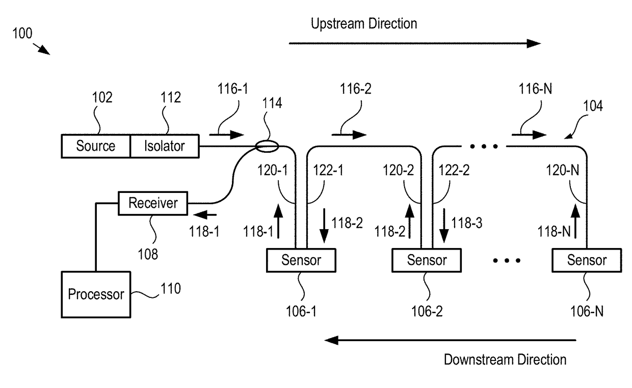
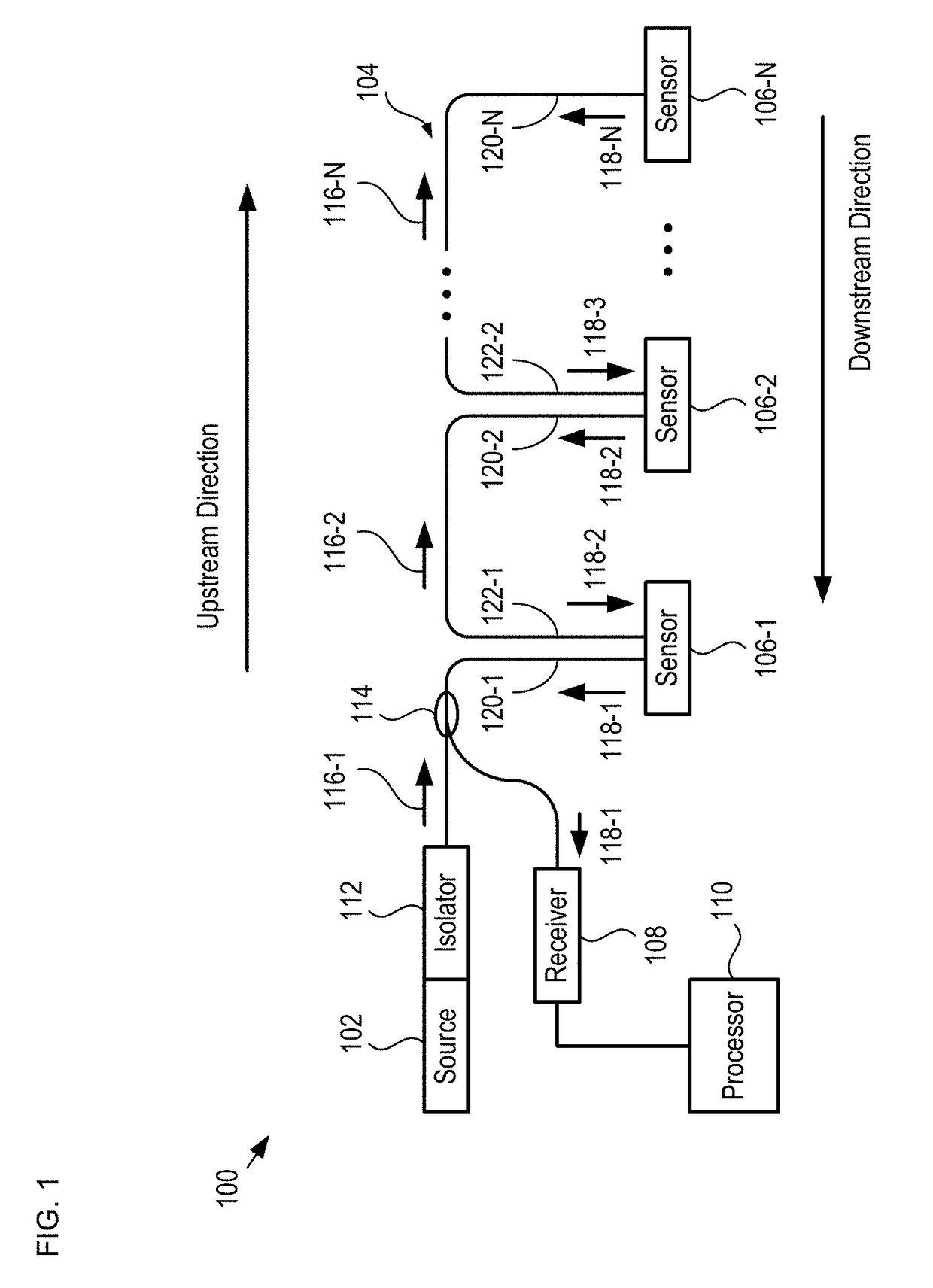
[0023]FIG. 1 depicts a schematic drawing of a sensor network in accordance with an illustrative embodiment of the present invention. Network 100 is a distributed pressure-sensor network operative for providing a spatial map of pressure based on measurements made at N locations. In some embodiments, network 100 is operative for monitoring a plurality of measurands at one or more locations. In some embodiments, network 100 is operative for monitoring one or more measurands at one or more locations. For the purposes of this Specification, including the appended claims, a “measurand” is defined as the quantity measured by a sensor.

[0024]Network 100 includes source 102, fiber bus 104, sensors 106-1 through 106-N, receiver 108, and processor 110, interrelated as shown. It will be clear to one skilled in the art, after reading this Specification, how to specify, make, and use alternative embodiments wherein a network includes any practical number of sensors.

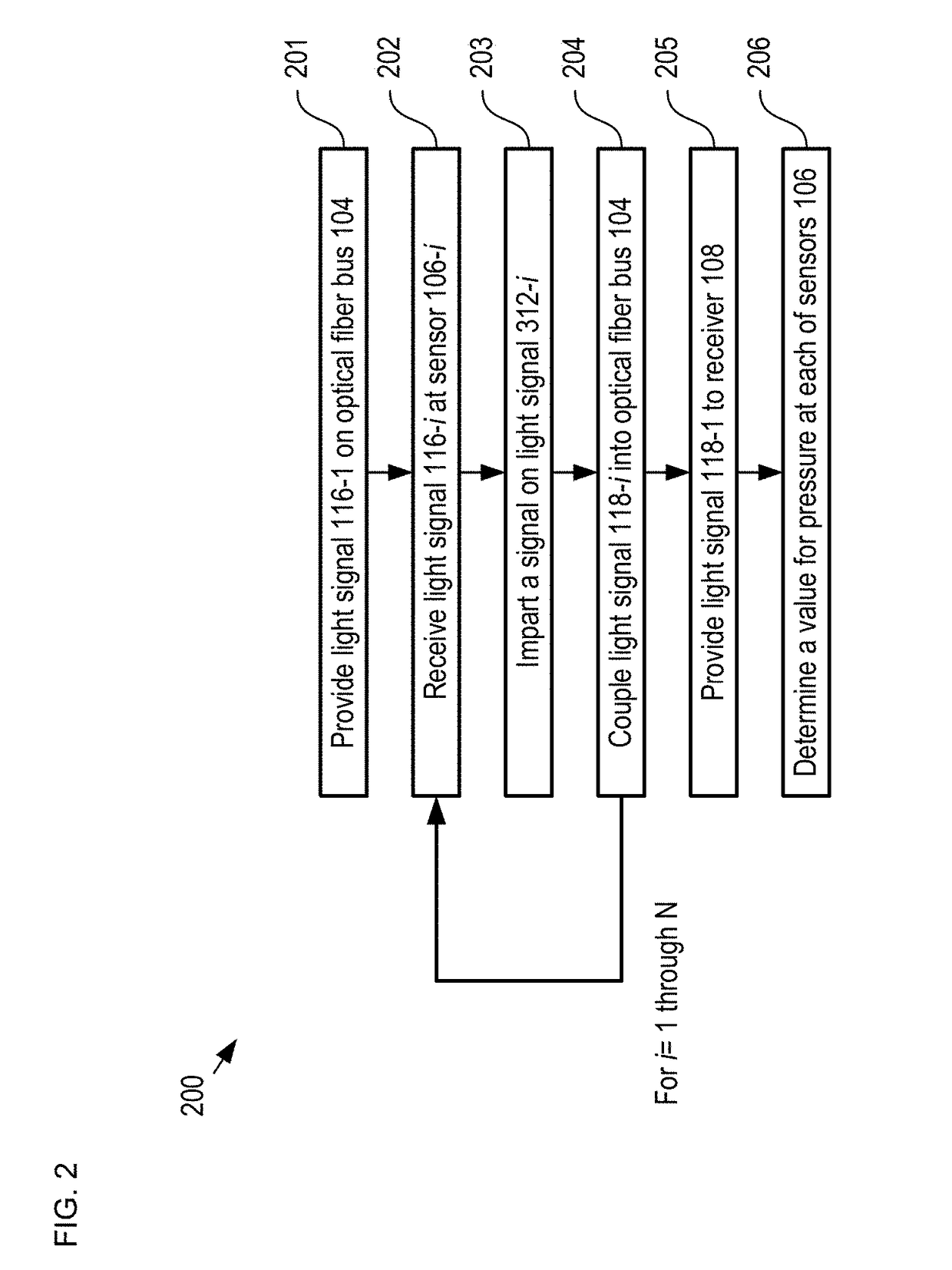
[0025]FIG. 2 depicts operations ...


PUM

PropertyMeasurementUnit
mirror reflectanceaaaaaaaaaa
cavity lengthaaaaaaaaaa
wavelengthaaaaaaaaaa

Abstract

A sensor network having a series arrangement of fiber-coupled, reflective sensors is disclosed. In operation, a first light signal having multiple wavelength bands is launched in an upstream direction on a fiber bus. Each sensor includes a wavelength filter and an FP sensor that is sensitive to a parameter. Each wavelength filter (1) selectively passes a different one of the wavelength bands to its FP sensor and (2) reflects the remaining wavelength bands back into the fiber bus to continue upstream. The FP sensor imprints a signal based on the parameter onto its received light and reflects it as a second light signal. The collimator, wavelength filter, and FP sensor of each sensor are arranged such that each second light signal is returned to the fiber bus, which conveys them in a downstream direction to a processor that measures them and estimates the parameter at each sensor.

Description

RELATED APPLICATIONS[0001]This application is a continuation of co-pending U.S. patent application Ser. No. 14 / 602,563 (Attorney Docket: 3038-001US1), filed Jan. 22, 2015, which claims the benefit of U.S. Provisional Application No. 61 / 930,068 filed Jan. 22, 2014 (Attorney Docket: 3038-001PR1). The entire disclosure of each of U.S. patent application Ser. No. 14 / 602,563 and U.S. Provisional Application No. 61 / 930,068 is incorporated herein by reference.FIELD OF THE INVENTION[0002]The present invention relates to sensors in general, and, more particularly, to optical sensing systems.BACKGROUND OF THE INVENTION[0003]A sensor is a device that is designed to detect changes in a quantity (i.e., a measurand) and provide a corresponding output. All-optical, fiber-coupled sensors have many advantages over many other conventional sensors (e.g., acoustic sensors, etc.), such as small size and weight, ability to operate in chemically and / or electrically harsh environments, ease of multiplexing...

Claims


Application Information

Patent Timeline
Patent Type & Authority Applications(United States)
IPC IPC(8): G01D5/26G01H9/00G01D5/353G01L9/00
CPCG01D5/268G01D5/35383G01D5/35306G01D5/266G01H9/004G01L9/0079G01D5/35312
Inventor CARR, DUSTIN WADE
Owner LUNA INNOVATIONS
Why Eureka
Try Eureka