

Phase confocal method for near-field microwave imaging
a phase confocal and near-field microwave technology, applied in the field of microwave detection and near-field microwave imaging, can solve the problems of inaccurate flight time estimation and degrade image quality, and achieve accurate delay (or shift), accurate delay, and accurate estimation.
- Summary
- Abstract
- Description
- Claims
- Application Information
AI Technical Summary
Benefits of technology
Problems solved by technology
Method used
Image

Examples
Embodiment Construction
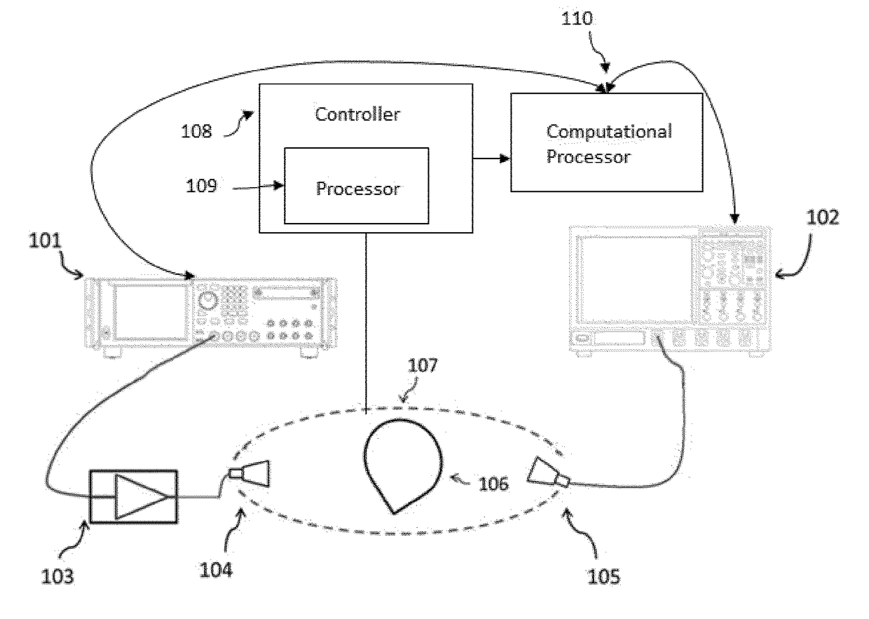
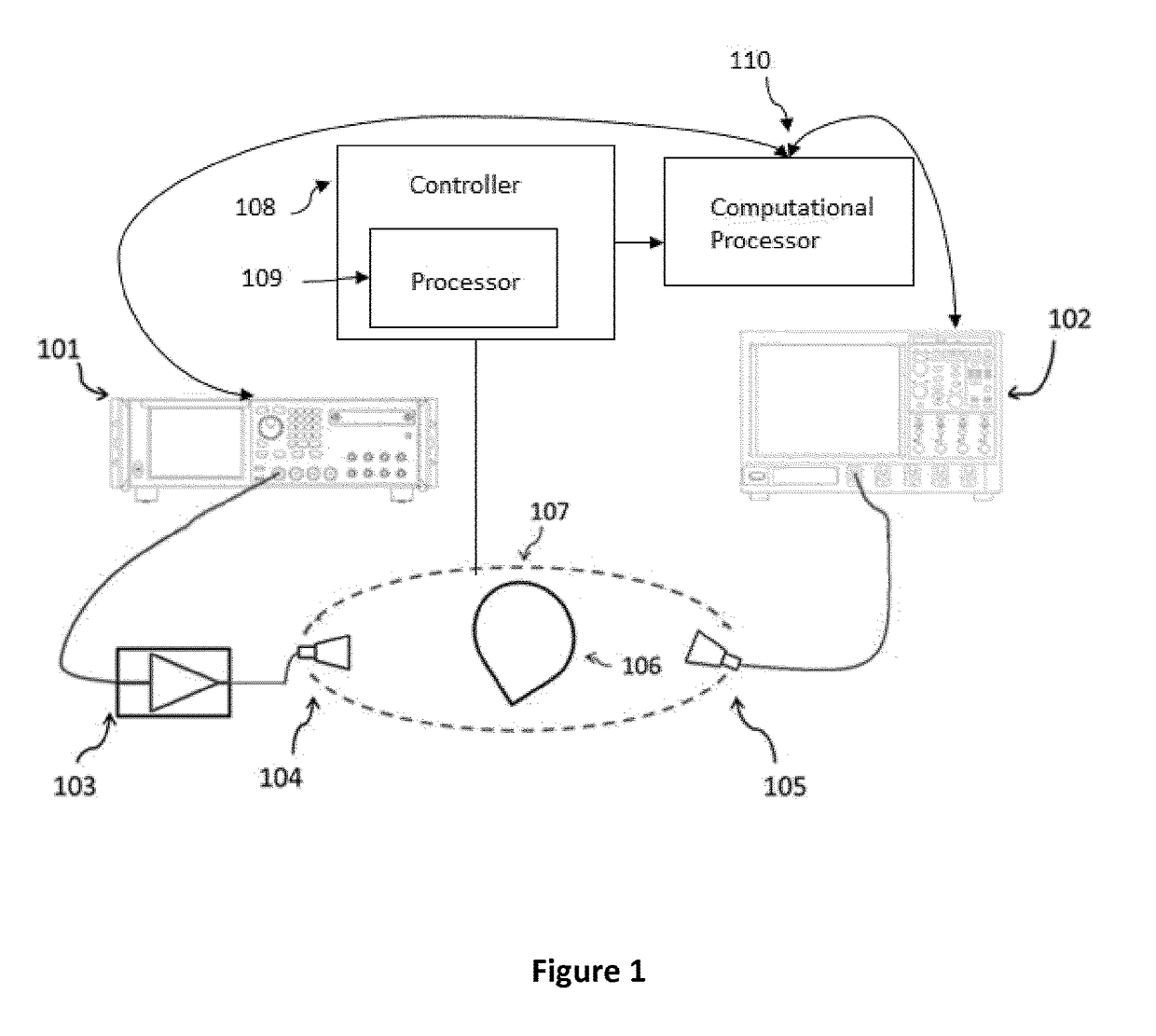
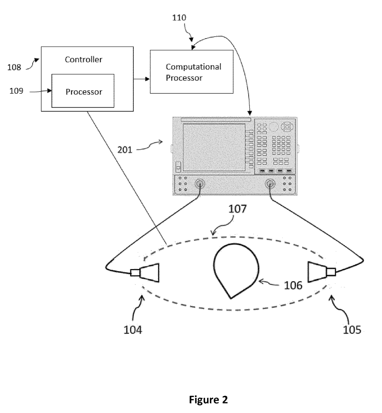
[0025]The measurement process can be carried out either in the time domain or in the frequency domain. When measurements are carried out in the time domain, a system as illustrated in FIG. 1 is typically used for electromagnetic signal collection. The transmitter 104 and the receiver 105 are usually UWB antennas which can individually move along a rail system 107 to send / receive a signal in many positions. A time-domain signal that has a wide-band characteristic is produced by a waveform generator 101. By amplifying the signal with a wide-band amplifier 103, the electromagnetic energy radiated by the transmitter antenna 104 is large enough for detection. The scattered signal of the object 106 is received by at least one receiver antenna 105 and then recorded on an oscilloscope 102. The object 106 may be in air, in a coupling medium, or within another object. By moving the transmitter 104 and the receiver 105 on the rail system 107, the object 106 is fully observed. A controller 108 ...
PUM
 Abstract
Description
Claims
Application Information