Wireless power transfer coil system using offset of electric and magnetic coupling for frequency splitting suppression

a technology of electric and magnetic coupling and frequency splitting suppression, which is applied in the direction of transformer/inductance coil/winding/connection, circuit arrangement, etc., can solve the problems of reducing system efficiency, limiting the operating life of devices, and great hidden safety problems of living and life, so as to maintain high efficiency, the effect of not increasing the cost of the system

Inactive Publication Date: 2017-12-14
SOUTH CHINA UNIV OF TECH
View PDF4 Cites 3 Cited by
  • Summary
  • Abstract
  • Description
  • Claims
  • Application Information

AI Technical Summary

Benefits of technology

[0012](1) the wireless power transfer coil system according to the present invention could maintain high-efficiency by self-adaptively adjusting the coupling degree according to the transmission distance, which doesn't need to add additional control circuit, therefore the cost of the system will not be increased, meanwhile, the system is simpler and is

Problems solved by technology

Conventional power transfer mainly depends on a form of wire connection, but wires occupy large amounts of space resources, consume large quantities of metal resources, meanwhile easily produce contacting electric spark, and cause great hidden safety problems to living and life.
In addition, in some utilization occasions, the wires could not be utilized for power transfer, but the using of batteries greatly restricts the operating life of devices.
However, the disadvantage of this system is that a fixed di

Method used


Image

  • Wireless power transfer coil system using offset of electric and magnetic coupling for frequency splitting suppression
  • Wireless power transfer coil system using offset of electric and magnetic coupling for frequency splitting suppression
  • Wireless power transfer coil system using offset of electric and magnetic coupling for frequency splitting suppression

Examples


embodiment

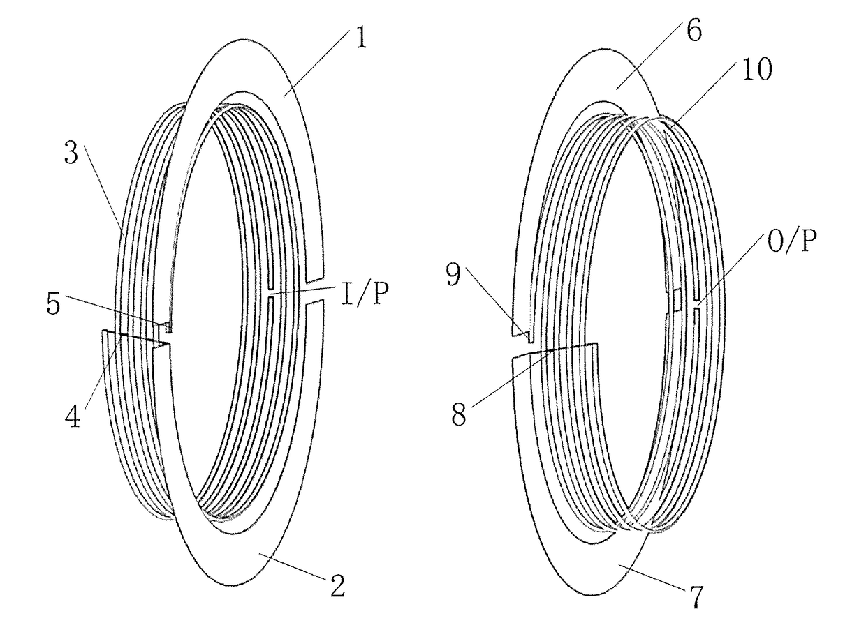
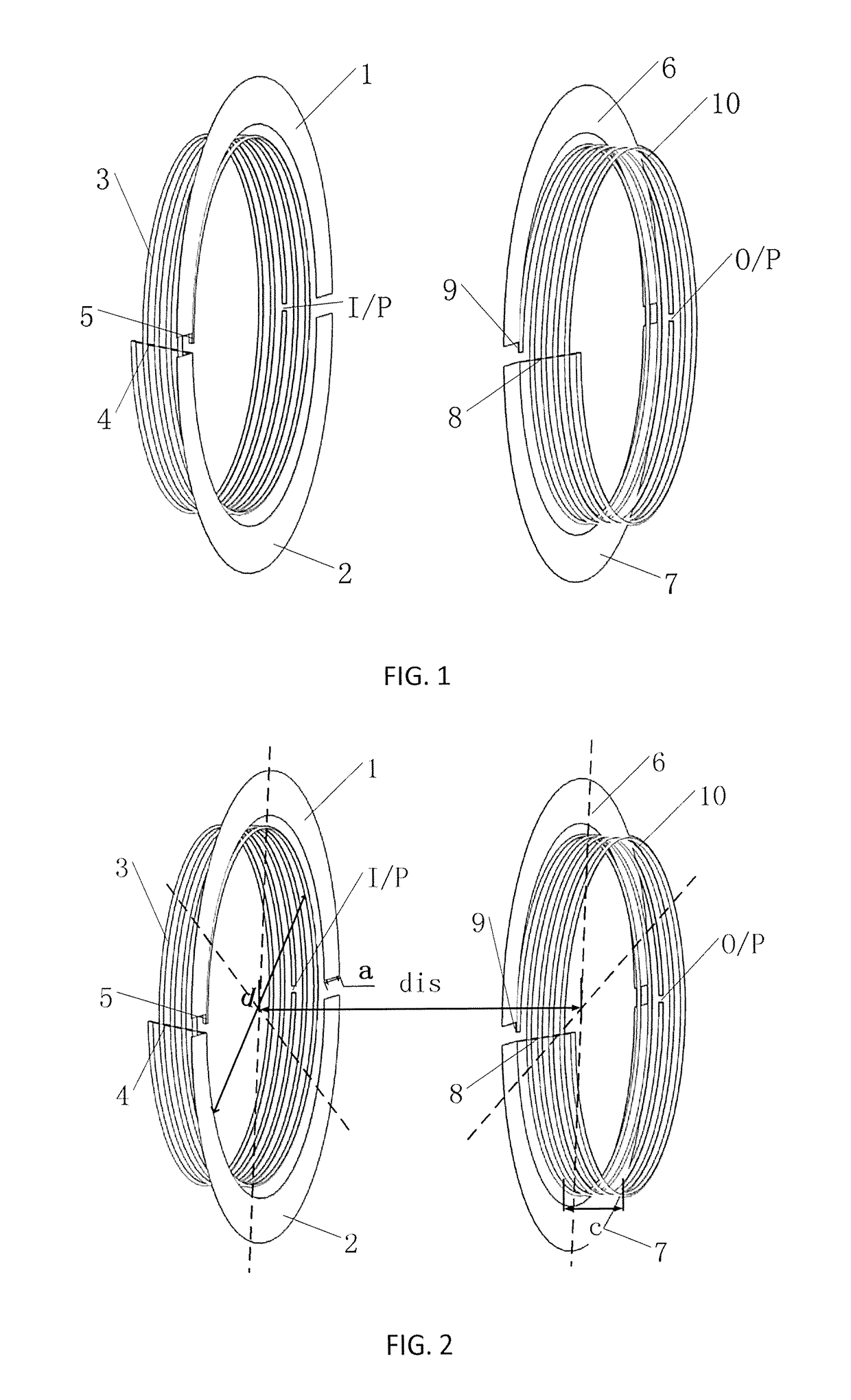
[0019]A structure of a wireless power transfer coil system using offset of electric and magnetic coupling for frequency splitting suppression is shown in FIG. 1. Related dimensions are shown in FIG. 2, wherein a thickness of the selected metal sheet is 2 mm, a distance between the coils is dis, and the specific circuit dimensions are selected as follows: the diameter d of the coil=185 mm, the width a of the metal sheet=25 mm, the thickness c of the coil=30 mm, the diameter r of the coil copper wire=2 mm, and the total dimension is 235 mm×235 mm.

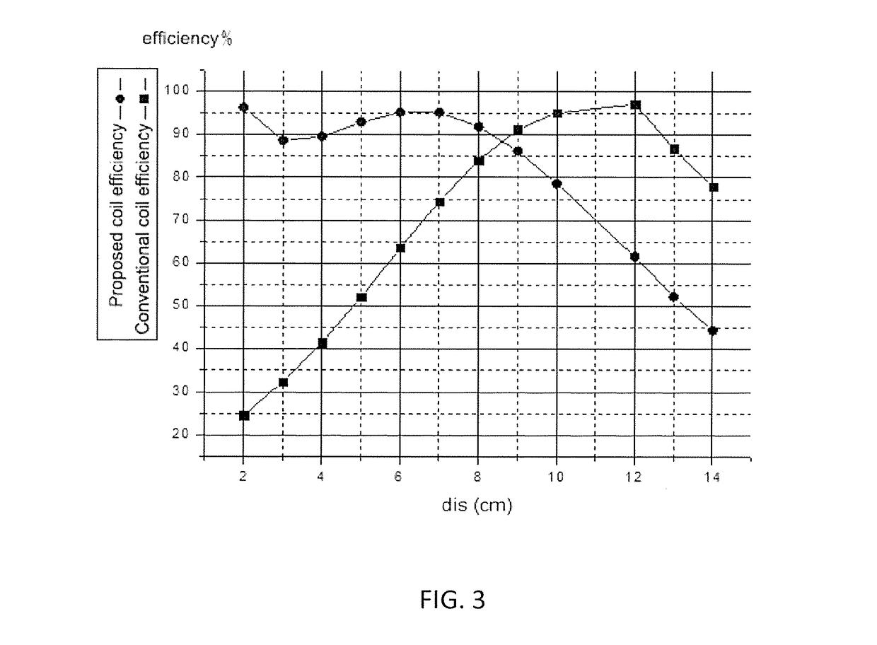
[0020]FIG. 3 is a simulation result of transmission efficiency of the coil system changing with distance, from which it can be seen that, the original coils have an efficiency over 80% only within 8 cm to 14 cm, and the variable distance range is only 6 cm, and the efficiency sharply reduces when the coils are close. However, the improved coils have a transmission efficiency over 80% within 0 to 10 cm, and the variable distance range is 10 cm...


PUM


Abstract

A wireless power transfer coil system using offset of electric and magnetic coupling for frequency splitting suppression, which includes one transmitting coil, one receiving coil and four loaded annular metal sheets, is provided. A first annular metal sheet and a second annular metal sheets of the four loaded annular metal sheets are loaded between the transmitting coil and a third and a fourth annular metal sheets of the four loaded annular metal sheets are loaded between the receiving coil to expand a variable distance range of a power transmission. The coil system enables the coils to worked in a state of magnetic and electric coupling. During a process of moving from a long distance to a short distance, a coupling coefficient between the coils changes gradually, but a low coupling degree is still maintained so that a phenomenon of frequency splitting is not produced, thereby maintaining a high-efficiency power transmission within the system.

Description

TECHNICAL FIELD[0001]The present invention relates to a technical field of high-efficiency wireless power transfer systems with a variable distance, and specifically relates to a wireless power transfer coil system using offset of electric and magnetic coupling for frequency splitting suppression.BACKGROUND[0002]Conventional power transfer mainly depends on a form of wire connection, but wires occupy large amounts of space resources, consume large quantities of metal resources, meanwhile easily produce contacting electric spark, and cause great hidden safety problems to living and life. In addition, in some utilization occasions, the wires could not be utilized for power transfer, but the using of batteries greatly restricts the operating life of devices. Under such backgrounds, people start trying a new power transfer technology, that is, wireless power transfer technology.[0003]In 2007, scientific research personnel at Massachusetts Institute of Technology firstly utilized magneti...

Claims


Application Information

Patent Timeline
IPC IPC(8): H01F27/34H01F27/28H02J50/10H02J50/70
CPCH01F27/34H01F27/28H02J50/70H02J50/10H01F38/14H02J50/12H04B5/0012H04B5/0037H04B5/0075
Inventor ZHANG, XIUYINXUE, CHENGDAILI, BIN
Owner SOUTH CHINA UNIV OF TECH
Why Eureka
Try Eureka