Hybrid solar generator

Active Publication Date: 2017-12-14
GE AVIATION SYST LLC
View PDF7 Cites 13 Cited by
  • Summary
  • Abstract
  • Description
  • Claims
  • Application Information

AI Technical Summary

Problems solved by technology

Unfortunately, the electrical conversion process produces waste heat which is often not utilized in certain applications, such as in an aircraft that depends on solar energy for its operation or propulsion.
For example, there may be a lack of synergy between the PETE generator and other systems consuming

Method used


Image

  • Hybrid solar generator
  • Hybrid solar generator
  • Hybrid solar generator

Examples


Embodiment Construction

[0011]As may be appreciated, based on the disclosure, there exists a need in the art for higher conversion efficiencies in the electrical generators that convert solar radiation to electricity. Also, there exists a need in the art for a more efficient utilization of the heat available from solar radiation. Additionally, there exists a need in the art for an integration of solar generators with other power systems on an aircraft, such as other sources and sinks of heat.

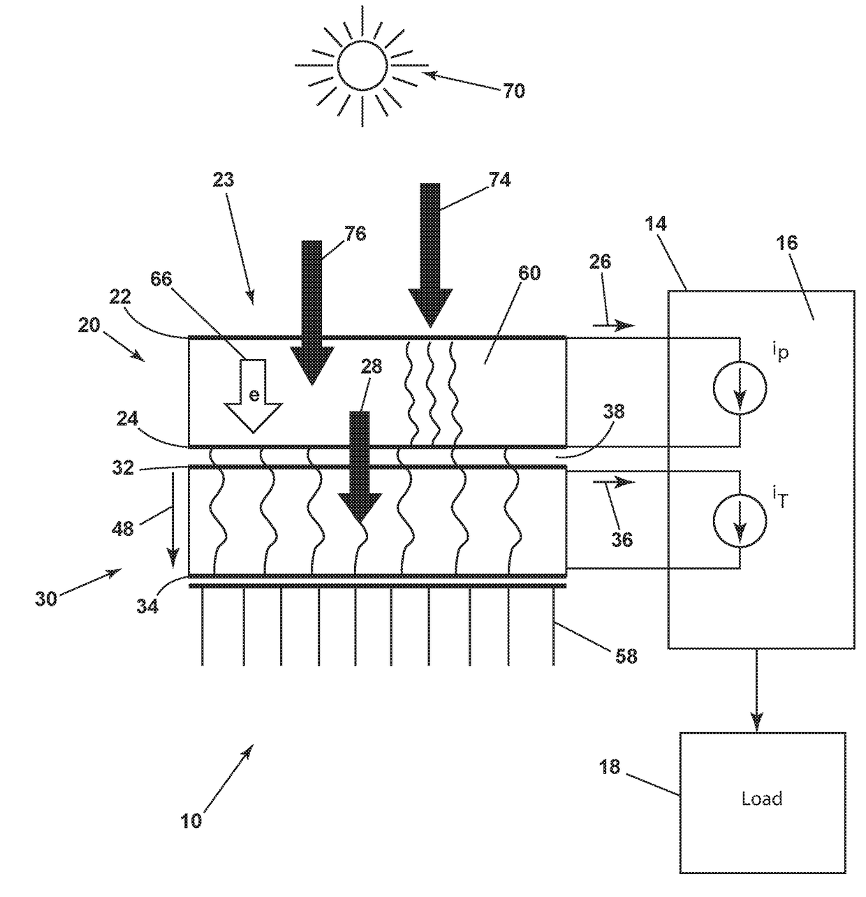
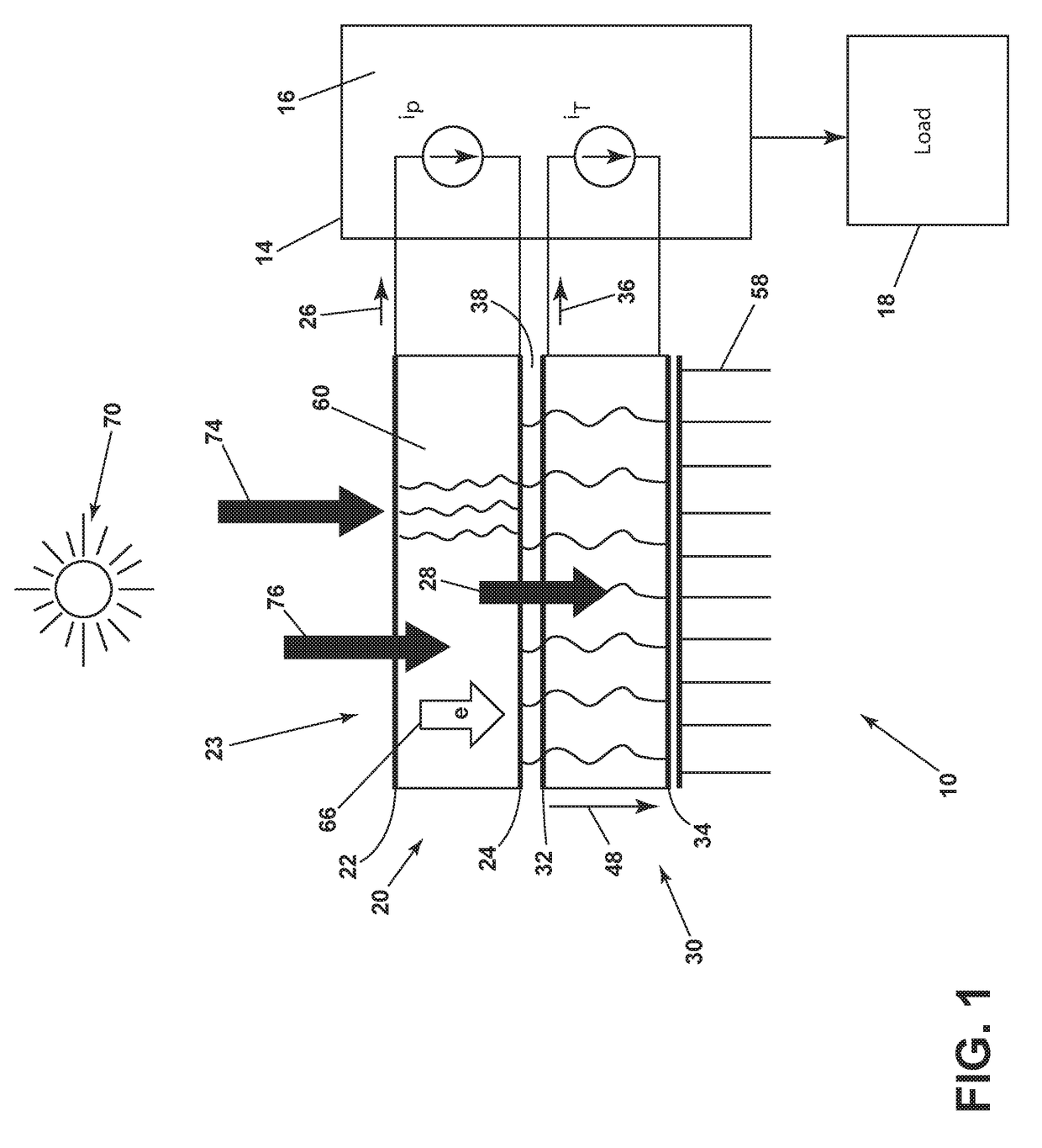
[0012]Referring to FIG. 1, in one aspect of the present disclosure, a solar generator 10 can include a photon-enhanced thermionic emission (PETE) generator 20 having a cathode 22 to receive solar radiation 70 and an anode 24 that in conjunction with the cathode 22 generates a first current 26 (iP) and waste heat 28 from the solar radiation 70. A flow of electrons 66 can be stimulated by visible light 76 transferring photons (not shown) and infrared light 74 transferring heat 78 into the PETE generator 20. There can be ...


PUM


Abstract

A solar generator can include a photon-enhanced thermionic emission generator with a cathode to receive solar radiation. The photon-enhanced thermionic emission generator can include an anode that in conjunction with the cathode generates a first current and waste heat from the solar radiation. A thermoelectric generator can be thermally coupled to the anode and can convert the waste heat from the anode into a second current. A circuit can connect to the photon-enhanced thermionic emission generator and to the thermoelectric generator and can combine the first and the second currents into an output current.

Description

BACKGROUND OF THE INVENTION[0001]The photon-enhanced thermionic emission (PETE) generator is a semiconductor-based device converting both the photonic and thermal energies of solar radiation to electricity at a higher conversion efficiency than conventional photovoltaic cells. Typically a vacuum gap is required between the cathode and the anode, and the PETE device operates most efficiently at temperatures in excess of 200 degrees Celsius, the reference temperature for aircraft engine bleed air. Unfortunately, the electrical conversion process produces waste heat which is often not utilized in certain applications, such as in an aircraft that depends on solar energy for its operation or propulsion. For example, there may be a lack of synergy between the PETE generator and other systems consuming or generating energy on an aircraft. Also, the operating temperature may be unregulated which can reduce the conversion efficiency of the PETE, depending on an amount of incident solar radia...

Claims


Application Information

Patent Timeline
IPC IPC(8): H01J40/06H01L51/44H01G9/20H01J9/12H01J40/16H01J1/34
CPCH01J40/06H01J40/16H01L51/447H01J9/12H01G9/209H01J1/34H02S10/30B64D41/00H01J45/00F02C6/08Y02E10/542Y02E10/549H10N10/13F02C6/18H10K30/87
Inventor WANG, JOHN XIAOZHONG
Owner GE AVIATION SYST LLC
Why Eureka
Try Eureka