Supercharge Your Innovation With Domain-Expert AI Agents!

Lamp control device

a technology of control device and led light, which is applied in the direction of fixed installation, transportation and packaging, light and heating equipment, etc., can solve the problems of affecting the operation of the control device, the inability to control the control of the light, and the inability to control the light. , to achieve the effect of preventing the occurrence of a vehicle accident, facilitating regulation, and improving the driving stability

Active Publication Date: 2017-12-14
SILICON WORKS CO LTD
View PDF3 Cites 6 Cited by
  • Summary
  • Abstract
  • Description
  • Claims
  • Application Information

AI Technical Summary

Benefits of technology

The patent describes a device that controls the lights of a vehicle to improve its appearance. It does this by turning on the LED channels of the lights in a specific order, using a delay time. This helps to prevent accidents and improve driving stability by excluding certain LED channels that may be short-circuited or open. Overall, the device makes the vehicle's lights look better and safer.

Problems solved by technology

However, an LED driving device for driving LEDs has limitations in increasing the number of parts for controlling light emission of LEDs, in proportion to an increase in the number of LEDs, and in regularly disposing LEDs in conformity with the installation circumstances of a vehicle.
In the conventional lamp control device, a limitation may be caused in increasing the number of LED channels due to the installation circumstances of a vehicle, and an error may be caused in the offset between parts, arrangement of parts, etc.
Such an offset between parts may induce a current deviation between LED channels.
Attributable to the current deviation, a problem may be caused in the conventional lamp control device in that it is difficult to implement uniform brightness control between channels.
Further, in the case where a certain LED channel is open or shorted among a plurality of LED channels included in a vehicle lamp, problems such as power efficiency degradation and heat generation may be caused.
Due to this fact, power efficiency degradation may occur, and heat generation may increase as the temperature of an FET / BJT corresponding to a normal LED channel rises.
Because a rear combination lamp among vehicle lamps is installed on a rear portion of a vehicle body, it is difficult for a driver to frequently check whether the rear combination lamp operates normally.
If an LED adopted in a vehicle lamp does not operate normally, an accident may occur during driving since the driving intention of a vehicle cannot be appropriately indicated to trailing vehicles.

Method used


Image

  • Lamp control device
  • Lamp control device
  • Lamp control device

Examples


first embodiment

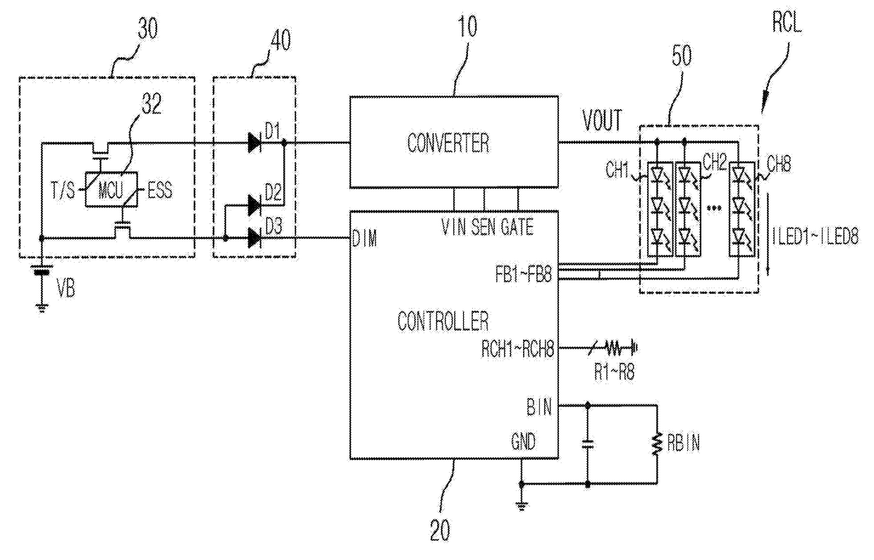
[0049]FIG. 1 is a representation of an example of a diagram to assist in the explanation of a lamp control device in accordance with the present disclosure.

[0050]Referring to FIG. 1, the lamp control device according to the first embodiment includes a lamp RCL, a converter 10 and a controller 20.

[0051]The lamp RCL includes one LED module 50 which has a plurality of LED channels. The plurality of LED channels in the LED module 50 may be configured in parallel. The first embodiment illustrated in FIG. 1 exemplifies that one controller 20 drives the LEDs of first to eighth channels CH1 to CH8 of the LED module 50. For instance, the lamp RCL includes a stop lamp, a tail lamp, a turn signal lamp and an emergency stop lamp of a vehicle, or is a rear combination lamp which may compositely realize the function of informing a stop, a turn and a sudden stop of the vehicle. The lamp RCL may be divided, depending upon a kind of a vehicle, into a type in which the ramp RCL is installed on only a...

second embodiment

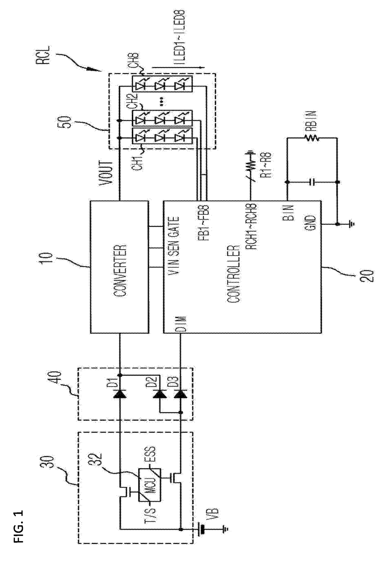
[0065]FIG. 2 is a representation of an example of a diagram to assist in the explanation of a lamp control device in accordance with the present disclosure, and FIG. 3 is a diagram illustrating a representation of an example of a turn signal lamp to which the lamp control device of FIG. 2 is applied.

[0066]Referring to FIG. 2, the lamp control device according to the second embodiment includes a lamp RCL, converters 10 and 12, and controllers 20 and 22.

[0067]The lamp RCL includes an LED module 50 and an LED module 52 each of which has a plurality of LED channels. The second embodiment exemplifies that the controller 20 drives the LEDs of first to eighth channels I_CH1 to I_CH8 of the LED module 50 and the controller 22 drives the LEDs of first to eighth channels O_CH1 to O_CH8 of the LED module 52. The lamp RCL may be divided, depending upon a kind of a vehicle, into a type in which the ramp RCL is installed on only a vehicle body and a type in which the lamp RCL is divisionally inst...

third embodiment

[0097]FIG. 7 is a representation of an example of a diagram to assist in the explanation of a lamp control device in accordance with the present disclosure.

[0098]Referring to FIG. 7, the lamp control device according to the third embodiment includes a lamp RCL, a converter 10 and a controller 20.

[0099]The lamp RCL includes an LED module 50 which has a plurality of LED channels. The plurality of LED channels in the LED module 50 may be configured in parallel. The third embodiment illustrated in FIG. 7 exemplifies that one controller 20 drives the LEDs of first to eighth channels CH1 to CH8 of the LED module 50.

[0100]A vehicle control unit 30 includes an MCU (micro control unit) 32, and controls a battery voltage VB to be transferred to the converter 10 in correspondence to a tail lamp signal TAIL and a stop signal STOP. Between the vehicle control unit 30 and the converter 10 and the controller 20, there may be disposed a path unit 40 including a path in which the battery voltage VB ...


PUM


Abstract

A lamp control device includes a converter configured to provide an output voltage and an internal voltage; a lamp including an LED module which has a plurality of LED channels, and configured to emit light in correspondence to the output voltage of the converter; and a controller configured to operate by using the internal voltage of the converter, control the output voltage of the converter to be retained at a level equal to or higher than a predetermined level, by using feedback voltages of the plurality of LED channels, and control channel currents of the plurality of LED channels to be regulated in correspondence to memory values which are set in advance.

Description

BACKGROUND1. Technical Field[0001]The present disclosure relates to a lamp control device, and more particularly, to a lamp control device for a vehicle, with improved stability and functionality.2. Related Art[0002]In general, an automobile includes vehicle lamps for various uses. The vehicle lamps may include a head lamp and a rear combination lamp.[0003]Among the vehicle lamps, a rear combination lamp includes a turn signal lamp, a stop lamp, a tail lamp and a back-up lamp, and is used as means for informing the driving intention and driving state of a vehicle to drivers of other vehicles.[0004]Recently, with the rapid development of a high brightness LED (light emitting diode), vehicle lamps adopting LEDs are being developed. Vehicle lamps adopting LEDs as light sources are diversified in their designs, and the numbers of LEDs used therein are being increased.[0005]However, an LED driving device for driving LEDs has limitations in increasing the number of parts for controlling l...

Claims


Application Information

Patent Timeline
Patent Type & Authority Applications(United States)
IPC IPC(8): H05B33/08F21S8/10B60Q1/30H05B44/00
CPCH05B33/0815B60Q1/30H05B33/0845F21S48/215F21S43/00F21V23/003F21V23/04H05B45/00B60Q1/382B60Q1/46B60Q11/00F21S43/14H05B45/46H05B47/165H05B45/325H05B45/395H05B45/10H05B47/17H05B45/375B60Q1/304B60Q1/381Y02B20/40H05B47/10H05B44/00
Inventor KIM, SUNG HWANHA, JOO WANYOO, SUN GEONJIN, HAI FENGLEE, JU HYUNQU, WANYUANLEE, SE WONJEONG, BYEONG HOHONG, JU PYO
Owner SILICON WORKS CO LTD
Features
  • R&D
  • Intellectual Property
  • Life Sciences
  • Materials
  • Tech Scout
  • Unparalleled Data Quality
  • Higher Quality Content
  • 60% Fewer Hallucinations
Learn More