Deposition apparatus and deposition method

a technology of deposition apparatus and deposition method, which is applied in the direction of additive manufacturing, manufacturing tools, coatings, etc., can solve the problems of high-power laser manufacturing cost, waste of materials, and low efficiency of the deposition apparatus, so as to reduce the cost of direct deposition process and greatly reduce the cost of laser

Inactive Publication Date: 2017-12-21
NAT CHENG KUNG UNIV
View PDF6 Cites 8 Cited by
  • Summary
  • Abstract
  • Description
  • Claims
  • Application Information

AI Technical Summary

Benefits of technology

[0007]Therefore, one objective of the present invention is to provide a deposition apparatus and a deposition method, which uses various lasers to simultaneously emit various laser beams toward a material supplied by an accommodating element. The deposition material can be applied with various laser beams simultaneously, such that the deposition material can be successfully melted into a deposition liquid without using a high power laser, and the cost of the laser can be greatly decreased, thereby reducing cost of a direct deposition process.

Problems solved by technology

However, the nozzles of the existing deposition apparatus have very low efficiency on depositing and laser melting procedures of the metal particles / powder, and the metal particles / powder are easily deposited by using the nozzles to result in waste of the material.
In addition, the current laser direct metal deposition technique typically uses a high power laser, and manufacturing cost of the high power laser is very expensive, thus resulting in high cost of the laser direct deposition processing.

Method used


Image

  • Deposition apparatus and deposition method
  • Deposition apparatus and deposition method
  • Deposition apparatus and deposition method

Examples


Embodiment Construction

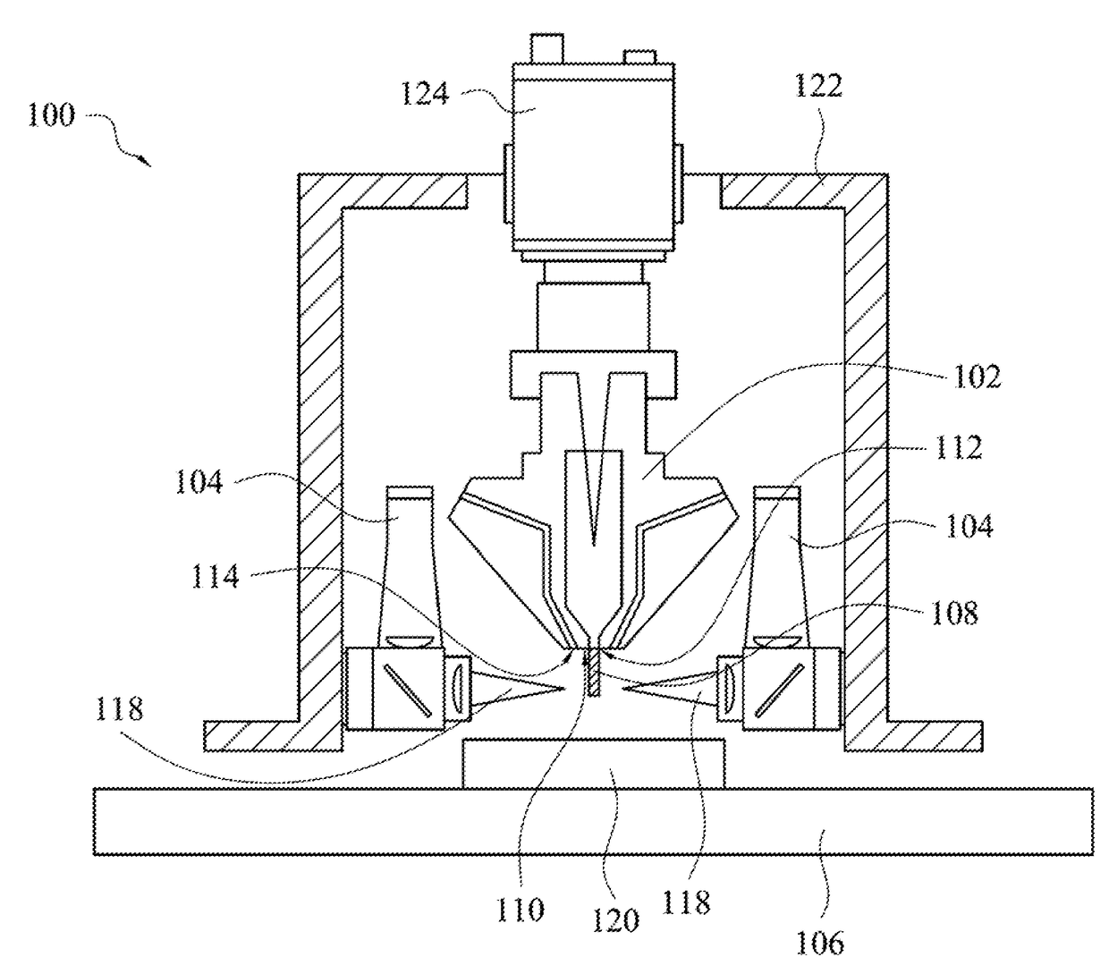
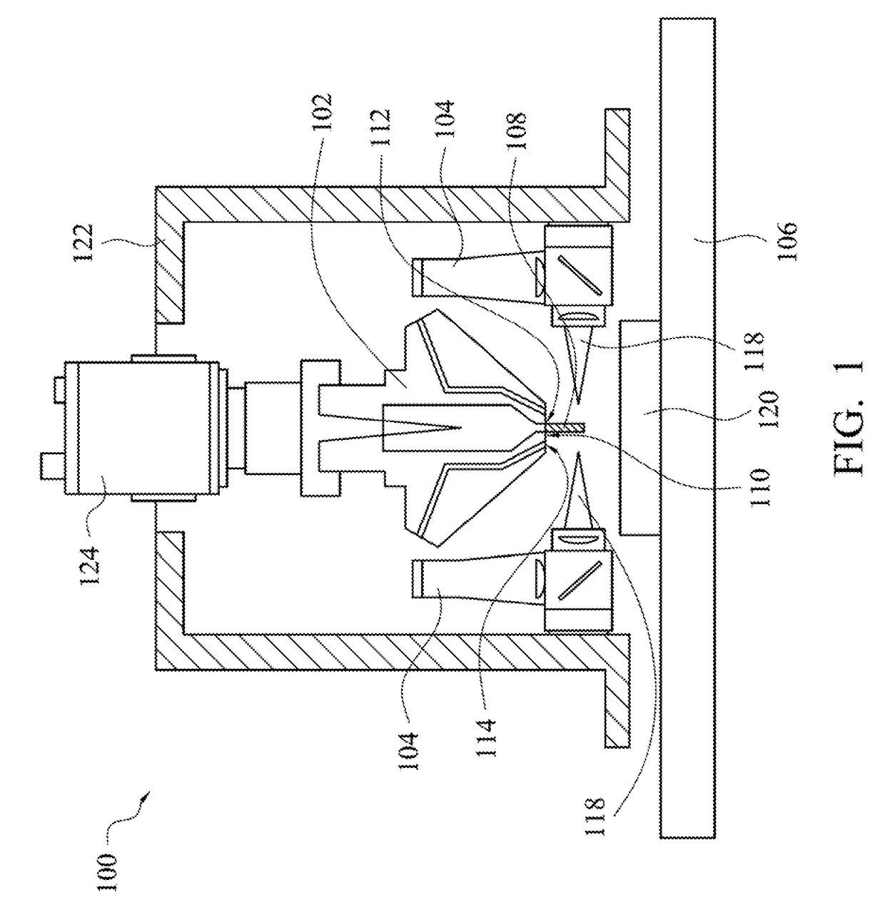
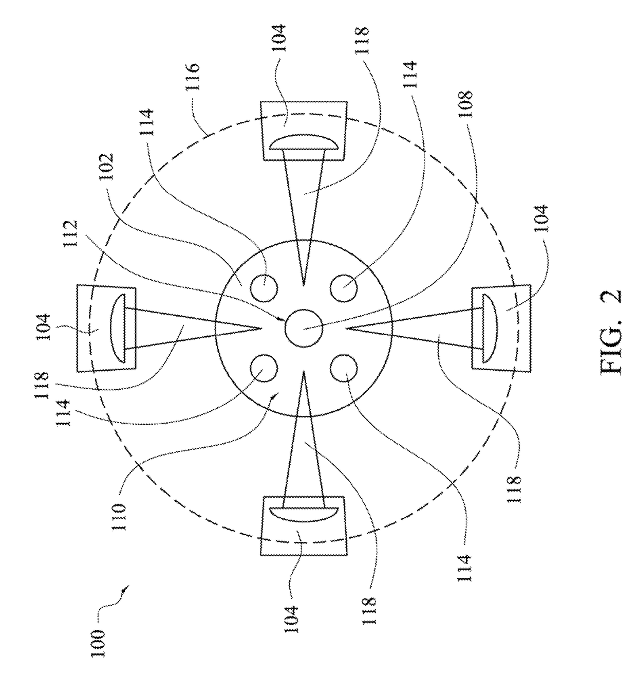
[0033]Referring to FIG. 1 and FIG. 2, FIG. 1 is a schematic drawing of a deposition apparatus in accordance with one embodiment of the present invention, and FIG. 2 is a bottom view showing an accommodating element and lasers of a deposition apparatus in accordance with one embodiment of the present invention. In the present embodiment, a deposition apparatus 100 may be a direct deposition apparatus, which can melt a deposition material and directly deposit the melted deposition material onto an object. In some examples, the deposition apparatus 100 may mainly include an accommodating element 102, a plurality of lasers 104 and a carrier 106.

[0034]The accommodating element 102 is mainly configured to accommodate and supply a material 108 for depositing. For example, the material 108 may be metal, or a combination of metal and nonmetal. As shown in FIG. 2, a bottom 110 of the accommodating element 102 may have a material supplying hole 112. In some examples, as shown in FIG. 1, the ma...


PUM

PropertyMeasurementUnit
powersaaaaaaaaaa
powersaaaaaaaaaa
depositionaaaaaaaaaa

Abstract

A deposition apparatus and a deposition method are described. The deposition apparatus includes an accommodating element, a plurality of lasers and a carrier. The accommodating element is configured to accommodate a material. The lasers are disposed at a periphery of the accommodating element, and are configured to simultaneously emit a plurality of laser beams toward the material to melt the material to form a deposition liquid. The carrier is disposed under the accommodating element and the lasers, and are configured to carry the deposition liquid.

Description

RELATED APPLICATIONS[0001]This application claims priority to Taiwan Application Serial Number 105119326, filed Jun. 20, 2016, which is herein incorporated by reference.BACKGROUNDField of Invention[0002]The present invention relates to a deposition apparatus and a deposition method. More particularly, the present invention relates to a direct deposition apparatus and a direct deposition method.Description of Related Art[0003]A direct metal deposition (DMD) technique is a laser technology, which can be used to manufacture high precise molds and high precise components, and also can be applied to modification, or tool and component repairing. Currently, a common direct metal deposition technique focuses an industrial laser beam on a substrate of a work piece to form a melted bath in the substrate of the work piece, and a metal powder is injected into the melted bath by using nozzles around the industrial laser. During the process, a control system removes the laser beam according to a...

Claims


Application Information

Patent Timeline
Patent Type & Authority Applications(United States)
IPC IPC(8): B23K26/34C23C4/123B23K26/146C23C6/00B23K26/144
CPCB23K26/34C23C4/123B23K26/146B23K26/144C23C6/00B33Y10/00B33Y30/00B23K26/342B23K26/702B23K26/123B22F10/00B22F12/90B22F10/36B22F12/45B22F10/22B22F12/53B22F10/37B23K26/0619C23C24/10Y02P10/25
Inventor HUANG, CHI-CHUANYANG, CHANE-YUANLIN, TZU-HSIANG
Owner NAT CHENG KUNG UNIV
Why Eureka
Try Eureka