Robotic system for confined space operations

a robotic system and confined space technology, applied in the field of robotics, can solve the problems of complex actuation, sensing and control system of devices, difficult to bring such devices into complex and confined geometries or environments, and limit the payload capability of end-tools, etc., and achieve the effect of increasing structural flexibility

Inactive Publication Date: 2017-12-21
ANSALDO ENERGIA IP UK LTD
View PDF0 Cites 19 Cited by
  • Summary
  • Abstract
  • Description
  • Claims
  • Application Information

AI Technical Summary

Benefits of technology

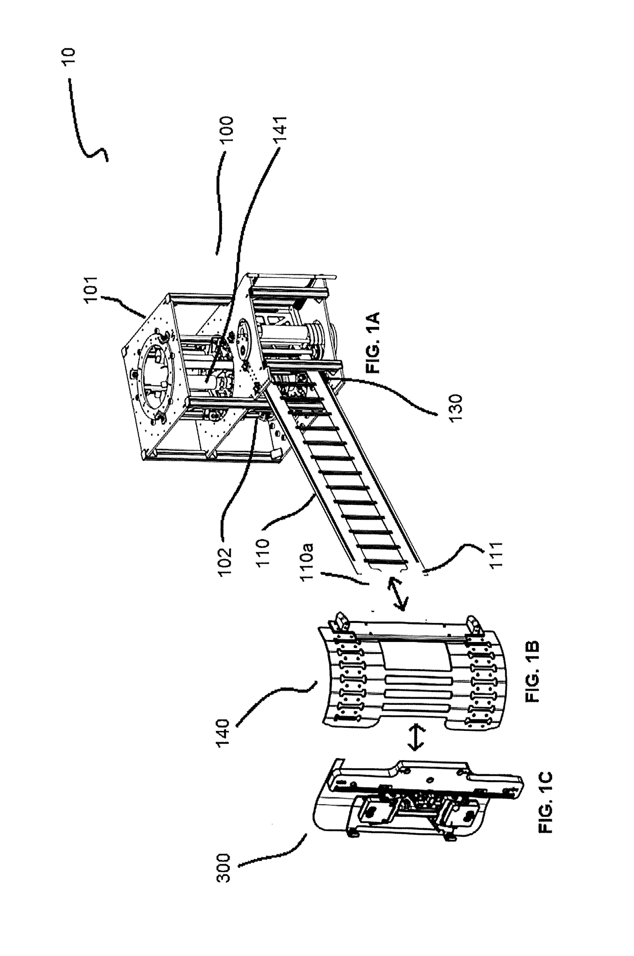
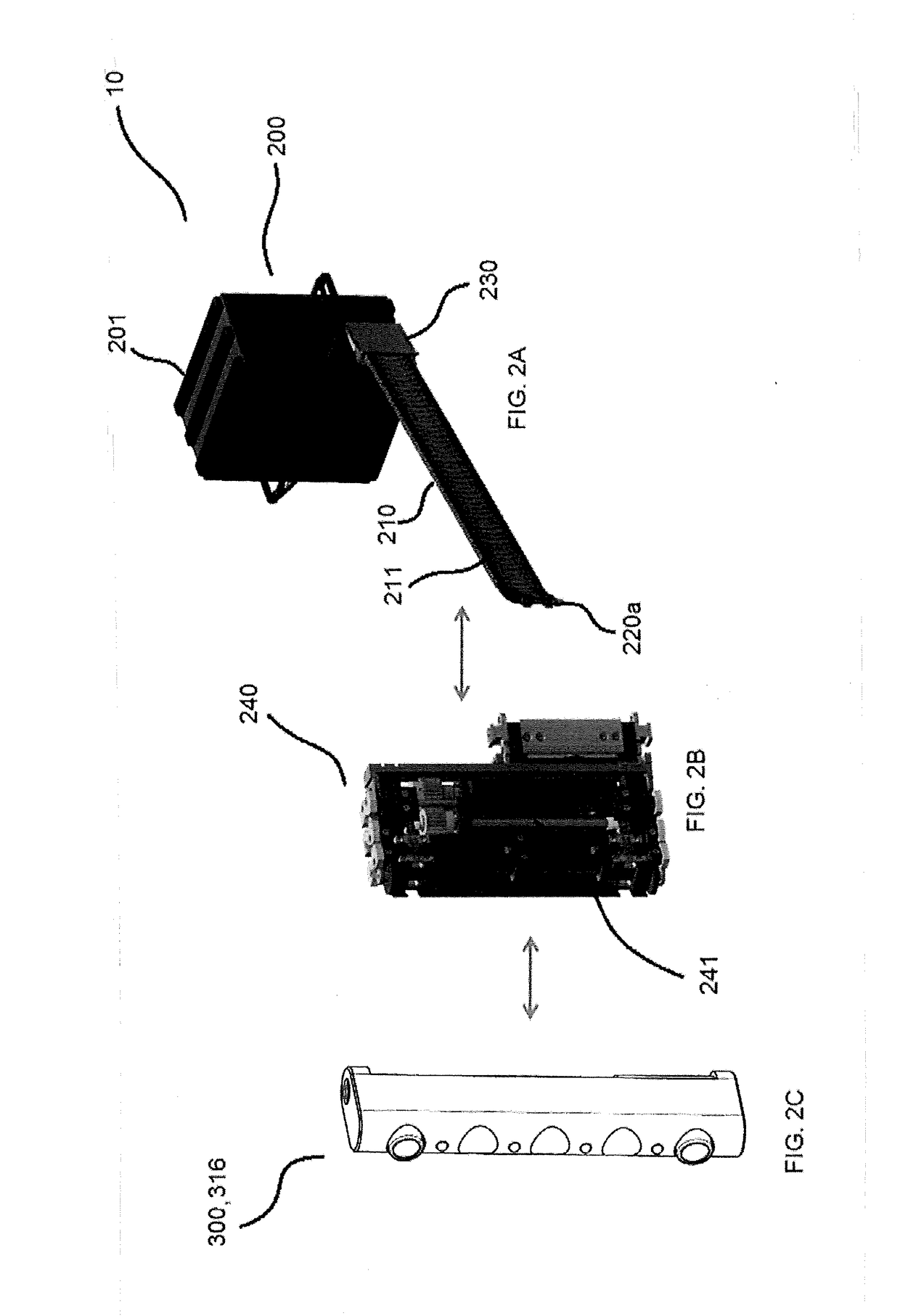
[0014]Finally, in this alternative embodiment, the head articulation unit may include a steering chain arrangement, having an interface end coupled to a free end of the extendable arm unit, a steering motor coupled to the steering chain arrangement, and a head roll joint coupled to the steering chain arrangement. In this embodiment, the head-roll joint enables an additional rotational degree of freedom aligned with the longitudinal axis of the extendable arm. It creates additional structural flexibility for this second more rigid embodiment of the non-actuated extendable arm unit which is inherent in the first, described embodiment. This rotational flexibility of the head articulation unit is expected to benefit applications where an end-tool needs to align with the orientation of different components in the confined space infrastructure.

Problems solved by technology

In spite of all of that, it has always been challenging to bring such devices into complex and confined geometries or environments.
However, the device requires a complex actuation, sensing and control system to achieve the targeted manipulation tasks.
This limits payload capabilities for an end-tool, achievable robustness as well as the minimal achievable dimensions for operations in confined space.

Method used


Image

  • Robotic system for confined space operations
  • Robotic system for confined space operations
  • Robotic system for confined space operations

Examples


Embodiment Construction

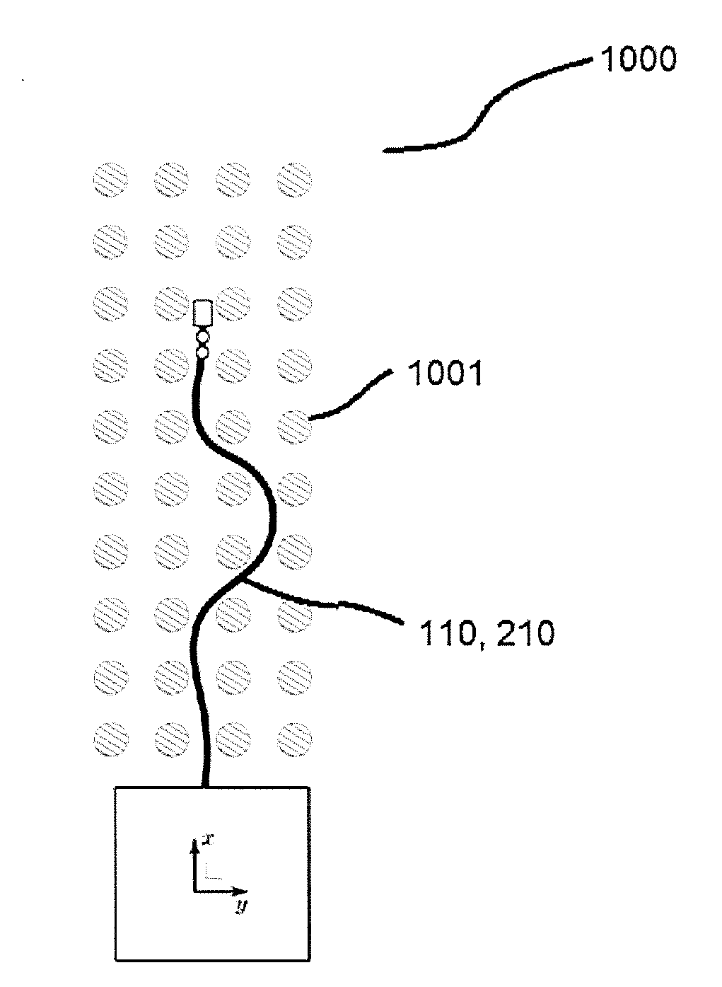
[0034]For a thorough understanding of the present disclosure, reference is to be made to the following detailed description, including the appended claims, in connection with the above-described drawings. In the following description, for purposes of explanation, numerous specific details are set forth in order to provide a thorough understanding of the present disclosure. It will be apparent, however, to one skilled in the art, that the present disclosure can be practiced without these specific details. In other instances, structures and devices are shown in block diagram form only, in order to avoid obscuring the disclosure. Reference in this specification to “one embodiment,”“an embodiment,”“another embodiment,”“various embodiments,” means that a particular feature, structure, or characteristic described in connection with the embodiment is included in at least one embodiment of the present disclosure. The appearance of the phrase “in one embodiment” in various places in the spec...


PUM


Abstract

A robotic system includes a main drive unit, a non-actuated extendable arm unit an axial drive unit, an arm guidance member, and a head articulation unit. The unit includes a mounting structure, and an arm storage unit coupled to the mounting structure. The arm unit is coupled to the arm storage unit to be moved axially in a lateral plane from the arm storage unit. The arm unit is flexible and thin in the lateral plane, and rigid and wide in a vertical plane. The unit may be coupled to the arm storage unit to enable axial extension and retraction of the unit. The head articulation unit is coupled to the arm unit to actuate thereto.

Description

PRIORITY CLAIM[0001]This application claims priority from European Patent Application No. 16175502.0 filed on Jun. 21, 2016, the disclosure of which is incorporated by reference.BACKGROUNDField of Endeavor[0002]The present disclosure relates generally to robotics and, more particularly, to a robotic device or system including robotic arms for an environment, including but not limited to, confined and complex geometries, e.g. given by pipework or turbine flow-paths in a power plant, for applications, such as, inspection, manipulation, and in-situ repair.Brief Description of the Related Art[0003]Robotic devices have been successfully utilized in many different applications, such as machining, assembly, inspection, repair and more. In spite of all of that, it has always been challenging to bring such devices into complex and confined geometries or environments. Conventional robotic devices may have the capability of accommodating various useful operations in non-confined geometries or ...

Claims


Application Information

Patent Timeline
Patent Type & Authority Applications(United States)
IPC IPC(8): B25J18/06B25J18/02B25J19/02
CPCB25J18/06Y10S901/44B25J18/02B25J19/023B25J9/065B25J9/104B25J9/1635B25J15/0066B25J15/0206B25J15/04
Inventor OTERO DEL REAL, ELENAFISCHER, WOLFGANGCARRASCO, EDGAR ERNESTOHUERZELER, CHRISTOPHPERALTA, ANDRESLOOSLI, DOMINILSCHNEIDER, THOMASMORRIS, THOMAS
Owner ANSALDO ENERGIA IP UK LTD
Why Eureka
Try Eureka