Micro electro-mechanical strain displacement sensor and usage monitoring system

a micro electro-mechanical and sensor technology, applied in the field of micro electro-mechanical strain displacement sensor and usage monitoring system, can solve the problems of difficult and costly deducting accurate and representative, over-reach that is often conducted prematurely, and reduce the cost of the overhaul, so as to improve the assessment of structural integrity and reduce the cost. , the effect of cost saving

Active Publication Date: 2017-12-21
IPR INNOVATIVE PROD RESOURCES
View PDF16 Cites 19 Cited by
  • Summary
  • Abstract
  • Description
  • Claims
  • Application Information

AI Technical Summary

Benefits of technology

[0085]The invention provides a cost effective, autonomous and extremely low power consumption strain history monitoring system capable of recording, processing and storing compressed data on the entire history of meaningful stress/strain event over many years of operation. Its small size and simplicity of inst

Problems solved by technology

Finally, in the absence of analysis of the real stresses to which a component has been subjected, the worst case scenario is always taken with respect to the possible damage that has occurred to the component, which can lead to overhauls that are often conducted prematurely.
Moreover, frequent overhauls can also introduce the additional possibility that an error may occur during re-assembly of the overhauled component during re-installation.
In some instances, data is collected by the inertial forces sensing unit of the airplane to determine whether the airplane has been subjected to exceptional stresses (such as a hard landing), however it can be diffi

Method used


Image

  • Micro electro-mechanical strain displacement sensor and usage monitoring system
  • Micro electro-mechanical strain displacement sensor and usage monitoring system
  • Micro electro-mechanical strain displacement sensor and usage monitoring system

Examples


Embodiment Construction

Best Mode

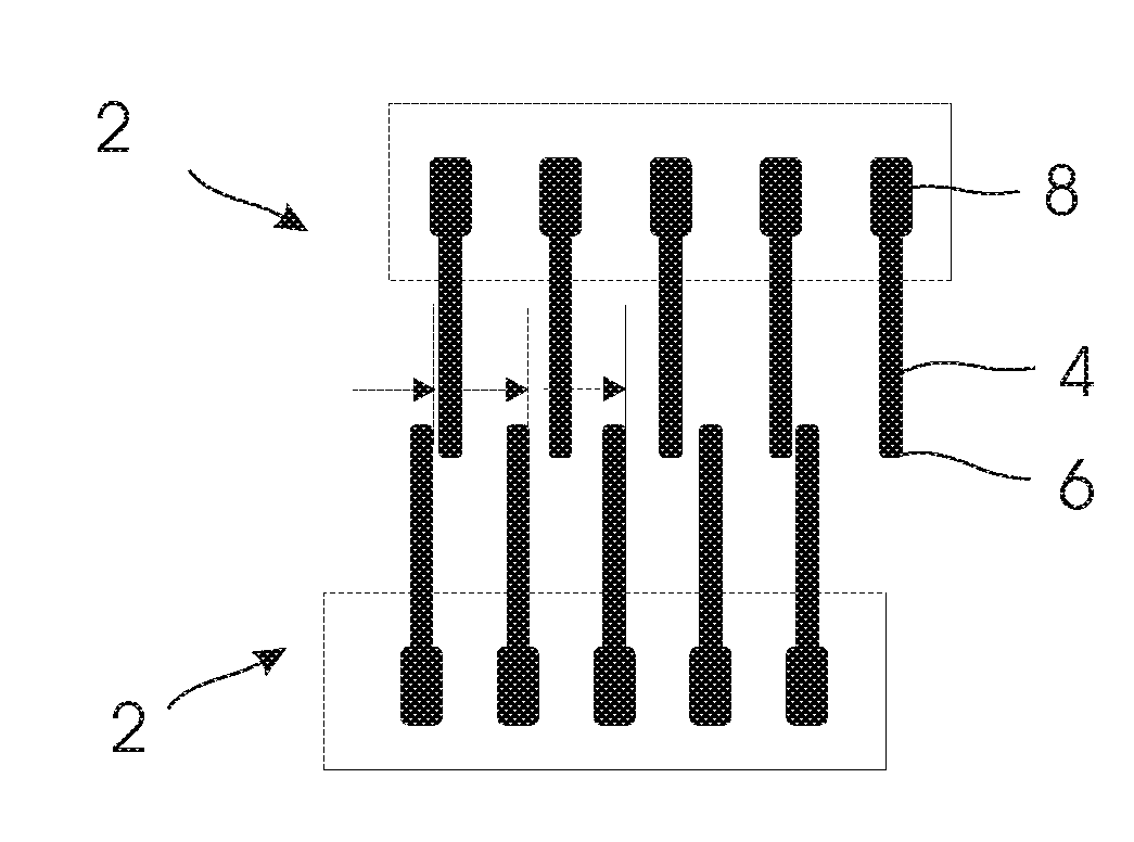
[0197]Best mode of the invention is generally illustrated by FIGS. 59 and 60. Two arrays of flexible micro or nano-scale cantilevers are in sequential contact between adjacent cantilevers spaced in a fashion incorporating Vernier approach. This configuration allows for larger gaps between the cantilevers which simplifies MEMS fabrication while preserving an overall high sensitivity of the sensor to a displacement. Any suitable means for conversion of the strain can be used to provide displacement to the sensor, including, but not limited to those described in FIGS. 35-41 or FIGS. 43 and 44. A variant of the algorithm of operation of the best mode of the invention is illustrated by FIG. 104.

MODE FOR THE INVENTION

Mode for Invention

[0198]In at least one embodiment the present invention relates to a system for monitoring and logging displacements related to mechanical stress conditions.

[0199]As will be a readily appreciated by the skilled person, all components discussed herein...


PUM


Abstract

A low power consumption multi-contact micro electro-mechanical strain/displacement sensor and miniature autonomous self-contained systems for recording of stress and usage history with direct output suitable for fatigue and load spectrum analysis are provided. In aerospace applications the system can assist in prediction of fatigue of a component subject to mechanical stresses as well as in harmonizing maintenance and overhauls intervals. In alternative applications, i.e. civil structures, general machinery, marine and submarine vessels, etc., the system can autonomously record strain history, strain spectrum or maximum values of the strain over a prolonged period of time using an internal power supply or a power supply combined with an energy harvesting device. The sensor is based on MEMS technology and incorporates a micro array of flexible micro or nano-size cantilevers. The system can have extremely low power consumption while maintaining precision and temperature/humidify independence.

Description

TECHNICAL FIELD[0001]The present invention relates to strain and displacement gauges. More specifically, the present invention relates to systems for the measurement and logging of strain or displacement history in a wide variety of applications, such as in mechanical components of a fixed or a rotary wing aircraft, civil structures, machines or vessels. It also can work as a stand-alone or integrated sensor or recording device for use in variety of applications where the measured parameter can cause a displacement such as accelerometers and bad cells.BACKGROUND ART[0002]In the aviation industry safety rules require that aircraft components are constantly monitored for fatigue as these components are subjected to a large number of significant and prolonged mechanical stresses (or loads). Accordingly, these components are subjected to overhauls on a regular and recurrent basis. A number of specific components, such as landing gears, engine pylons, etc. can conceivably benefit from a ...

Claims


Application Information

Patent Timeline
IPC IPC(8): G01L1/00G01L1/04G01M5/00
CPCG01L1/005G01L1/04B81B2201/02G01M5/0083G01M5/0033G01L1/044
Inventor OKULOV, PAUL D
Owner IPR INNOVATIVE PROD RESOURCES
Why Eureka
Try Eureka