Lighting device and display device

a technology of light source and display device, which is applied in the direction of optical light guide, instruments, optics, etc., can solve the problems of complex path of light reflecting off the exit light reflection portion and exiting through the light exit surface, and achieve the effect of reducing uneven luminance and improving luminan

Active Publication Date: 2017-12-21
SHARP KK
View PDF13 Cites 43 Cited by
  • Summary
  • Abstract
  • Description
  • Claims
  • Application Information

AI Technical Summary

Benefits of technology

[0027]According to the present invention, luminance is improved with reducing luminance unevenness and interference unevenness.

Problems solved by technology

Namely, a path of light reflecting off the exit light reflection portion and exiting through the light exit surface is complicated.

Method used


Image

  • Lighting device and display device
  • Lighting device and display device
  • Lighting device and display device

Examples


first embodiment

[0054]A first embodiment of the present invention will be described with reference to FIGS. 1 to 20. In the present embodiment, a liquid crystal display device 10 will be described as an example. X-axis, the Y-axis and the Z-axis may be present in the drawings and each of the axial directions represents a direction represented in each drawing. An up-down direction is referred to FIGS. 3 to 5 and an upper side and a lower side in the drawings correspond to a front side and a back side, respectively.

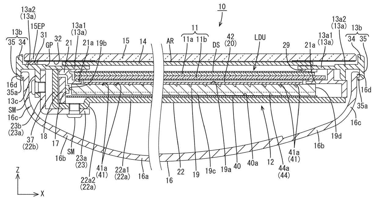
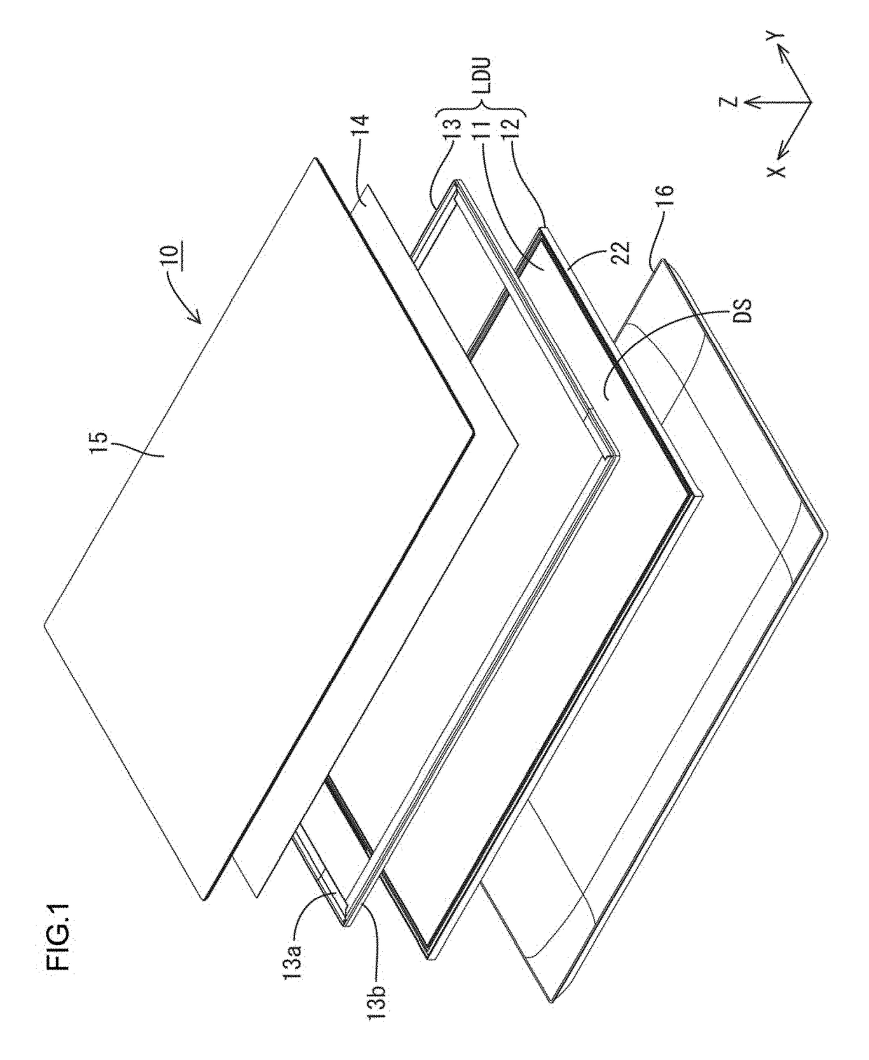
[0055]As illustrated in FIG. 1, the liquid crystal display device 10 has a rectangular plan-view shape as a whole, and includes a liquid display unit LDU that is a base component, and a touch panel 14, a cover panel (a protection panel, a cover glass) 15, and a casing 16 that are mounted in the liquid crystal display unit LDU. The liquid crystal display unit LDU includes a liquid crystal panel 11 (a display panel), a backlight device 12 (a lighting device), and a frame 13 (casing member). ...

second embodiment

[0132]Next, a second embodiment of the present invention will be described with reference to FIGS. 21 to 23. In the second embodiment, a configuration of an opposite plate surface-side convex lenticular lens portion 144 differs from that of the above embodiment. The configurations, operations, and effects that are similar to those in the first embodiment will not be described.

[0133]As illustrated in FIGS. 21 to 23, the opposite plate surface-side convex lenticular lens portion 144 includes opposite plate surface-side convex cylindrical lenses 144a. The opposite plate surface-side convex cylindrical lenses 144a include single opposite plate surface-side convex cylindrical lenses 46 (single opposite plate surface-side cylindrical lenses) and multiple continuous opposite plate surface-side convex cylindrical lenses 47 (continuous opposite plate surface-side cylindrical lenses). Flat portions 145 are disposed between the single opposite plate surface-side convex cylindrical lenses 46 wi...

third embodiment

[0135]Next, a third embodiment of the present invention will be described with reference to FIGS. 14 to 26. In the third embodiment, an opposite plate surface-side concave lenticular lens portion 48 is included for the opposite plate surface-side convex lenticular lens portion 44 of the first embodiment. The configurations, operations, and effects that are similar to those in the first embodiment will not be described.

[0136]As illustrated in FIGS. 24 to 26, a light guide plate 219 of the present embodiment includes the opposite plate surface-side concave lenticular lens portion 48 (an opposite plate surface-side anisotropic light collecting portion) on an opposite plate surface 219c. The opposite plate surface-side concave lenticular lens portion 48 includes opposite plate surface-side concave lenticular lenses 48a (an opposite plate surface-side unit light collecting portion, an opposite plate-side cylindrical lens) on the opposite plate surface 219c. The opposite plate surface-sid...


PUM

PropertyMeasurementUnit
apex angleaaaaaaaaaa

Abstract

A lighting device includes LEDs 17, a light guide plate 19, a reflection sheet 40, an exit light reflection portion 41 on a light exit surface 19a side of the light guide plate 19, opposite plate surface-side convex lenticular lens portions 44 and the flat portions 45 on the opposite plate surface 19c of the light guide plate 19. The occupied ratio of the opposite plate surface-side convex lenticular lens portions 44 with respect to the second direction is relatively low in a portion near the light entrance surface 19b in the first direction and is relatively high in a portion far away from the light entrance surface. The flat portions 45 have a relatively high occupied ratio to the opposite plate surface 19c with respect to the second direction in a portion near the light entrance surface 19b in the first direction and have a relatively low occupied ratio in a portion far away from the light entrance surface 19b.

Description

TECHNICAL FIELD[0001]The present invention relates to a lighting device and a display device.BACKGROUND ART[0002]In recent years, displays in image display devices are being shifted from conventional cathode-ray tube displays to thin display panels, such as liquid crystal panels and plasma display panels. With the thin displays, thicknesses of the image display devices can be decreased. Liquid crystal panels used for the liquid crystal display device do not emit light. Therefore, liquid crystal display devices including liquid crystal panels require backlight devices. The backlight devices are classified broadly into a direct type and an edge-light type based on mechanisms. The edge-light type backlight device includes a light source arranged on an edge portion, a light guide plate that guides light from the light source, and optical member that changes optical properties of light from the light guide plate and provides even planar light to the liquid crystal panel. A backlight devi...

Claims


Application Information

Patent Timeline
Patent Type & Authority Applications(United States)
IPC IPC(8): F21V8/00G02F1/1368G02F1/1362G02F1/1335G02F1/1333G02F1/1337
CPCG02F1/1337G02F1/133512G02B6/0055G02B6/0036G02B6/0053G02B6/0085G02B6/0091G02F1/133308G02F1/13338G02F1/133502G02F1/1368G02F1/136286G02F1/133514G02F2001/133302G02F2001/133331G02F2001/13629G02F2201/123G02F1/133528G02B6/0038G02B6/0061G02B6/0088G02B6/009G02F1/13629G02F1/133302G02F1/133331
Inventor HIRAYAMA, YOSHINOBUIMAOKU, TAKAOYAGI, SHUGO
Owner SHARP KK
Why Eureka
Try Eureka