Wireless power transmitter

Active Publication Date: 2017-12-21
ROHM CO LTD
View PDF0 Cites 20 Cited by
  • Summary
  • Abstract
  • Description
  • Claims
  • Application Information

AI Technical Summary

Benefits of technology

The patent describes a device that can detect foreign objects near a transmission antenna by measuring the frequency characteristics of the current that flows through a bridge circuit. This device is simpler and less expensive than conventional techniques, which use smoothing capacitors. The current sensor can also detect a current that flows to the ground, which improves detection precision. The technical effect of this patent is to provide a more effective and efficient solution for detecting foreign objects, which can prevent damage or interference in the transmission process.

Problems solved by technology

In a case in which wireless power supply is performed in such a state, a current flows through such a foreign object, leading to a problem of power loss.
Also, this leads to a problem of the foreign object heating up.

Method used


Image

  • Wireless power transmitter
  • Wireless power transmitter
  • Wireless power transmitter

Examples


first modification

[First Modification]

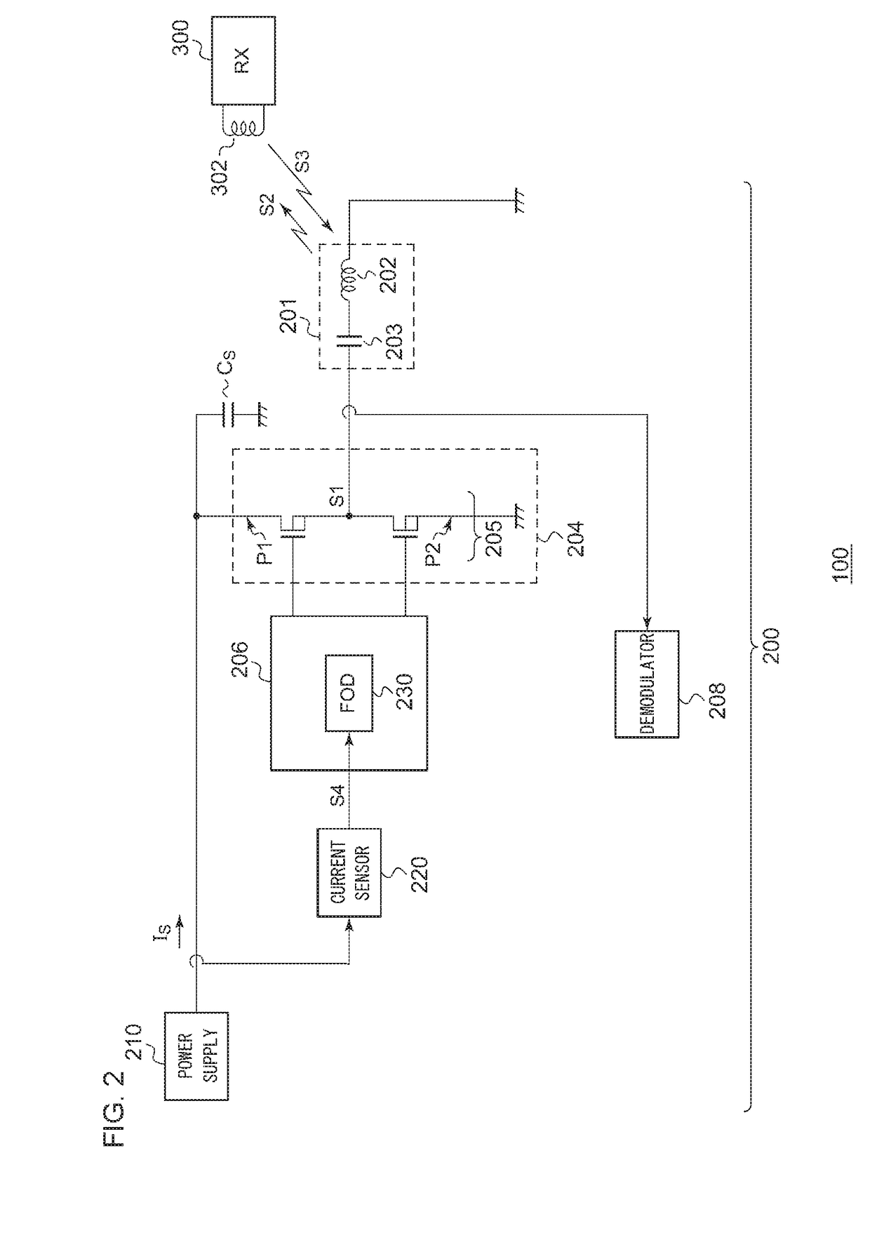
[0073]The current to be monitored by the current sensor 220 is not restricted to the input current IS of the bridge circuit. For example, the detection resistor RS may be arranged at a position that is closer to the ground side than the bridge circuit 205, for example. It should be noted that, in a case in which the current is measured on the ground side, the current smoothing effect of the smoothing capacitor CS cannot be expected. Accordingly, in some cases, such an arrangement requires an additional circuit and additional signal processing. It should be noted that, even in this case, such an arrangement also has an advantage of enabling a simple circuit configuration and simple signal processing as compared with a case in which the output current (i.e., coil current ICOIL) of the bridge circuit 205 is measured.

[0074]Furthermore, instead of the insertion of the detection resistor RS, the on resistance of the switching transistor (high-side transistor or otherwi...

second modification

[Second Modification]

[0075]Description has been made in the embodiment regarding the driver 204 for the half-bridge circuit. Also, the present invention is applicable to an H-bridge circuit.

third modification

[Third Modification]

[0076]Description has been made in the embodiment regarding an arrangement in which a foreign object is detected based on the Q value. However, the present invention is not restricted to such an arrangement. In other specifications that differ from the Qi standard or specifications that will be developed in the future, a foreign object may be detected based on the change in the center frequency f0 or the change in the bandwidth Δf instead of the Q value.


PUM


Abstract

A transmission antenna includes a resonance capacitor and a transmission coil coupled in series. A driver includes a bridge circuit that applies a driving voltage to the transmission antenna. A current sensor detects a current IS that flows through the bridge circuit. A foreign object detector detects the current IS that flows through the bridge circuit while changing the switching frequency applied to the bridge circuit. The foreign object detector judges the presence or absence of a foreign object based on the detection result.

Description

CROSS REFERENCE TO RELATED APPLICATIONS[0001]The present application is a continuation of PCT / JP2016 / 053042, filed on Feb. 2, 2016 and claims priority under 35 U.S.C. §119 to Japanese Patent Applications No. 2015-042687, filed on Mar. 4, 2015, the entire contents of which are both incorporated herein by reference.BACKGROUND OF THE INVENTION1. Field of the Invention[0002]The present invention relates to a wireless power supply technique, and particularly to foreign object detection.2. Description of the Related Art[0003]In recent years, in order to supply electric power to an electronic device, wireless power supply has begun to come into commonplace use. In order to advance the compatibility of products between manufacturers, the WPC (Wireless Power Consortium) has been organized, and the WPC has developed the Qi standard as an international standard.[0004]The wireless power supply that conforms to the Qi standard uses electromagnetic induction between a transmission coil and a rece...

Claims


Application Information

Patent Timeline
IPC IPC(8): H02J50/60H02J50/12H04B5/00
CPCH02J50/60H04B5/0093H04B5/0037H02J50/12H04B5/266H04B5/79G01V3/02
Inventor WATANABE, MASATOSHIMORINAGA, TOMOYA
Owner ROHM CO LTD
Why Eureka
Try Eureka