Hermetic structure and method of manufacturing the same

Inactive Publication Date: 2017-12-21
YOKOGAWA ELECTRIC CORP
View PDF3 Cites 2 Cited by
  • Summary
  • Abstract
  • Description
  • Claims
  • Application Information

AI Technical Summary

Benefits of technology

[0031]According to the present invention, it is possible to

Problems solved by technology

If that tensile strength exceeds the fracture stress of the glass members 326 or exceeds the adhesion strength of the glass adhesion surfaces, the hermetic structures are damaged.
However, since all of the

Method used


Image

  • Hermetic structure and method of manufacturing the same
  • Hermetic structure and method of manufacturing the same
  • Hermetic structure and method of manufacturing the same

Examples


Embodiment Construction

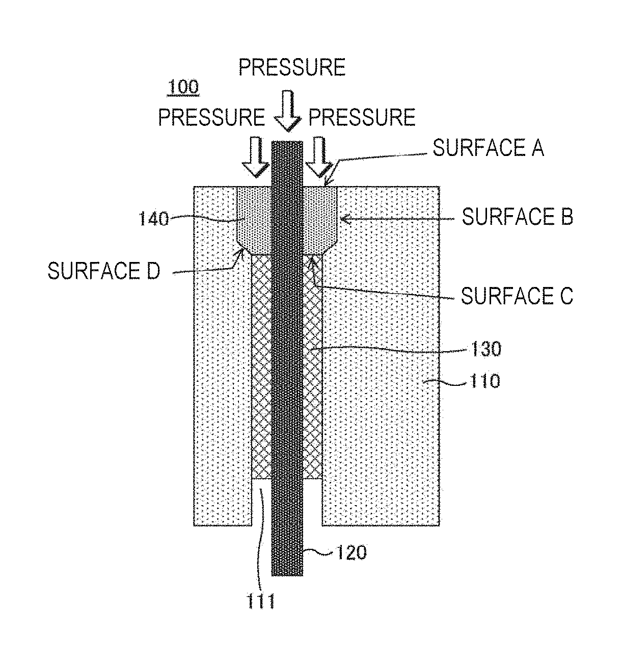
[0041]Hereinafter, an embodiment of the present invention will be described with reference to the accompanying drawings. FIG. 1 is a view illustrating an example of a hermetic structure of the present embodiment. The hermetic structure is suitable for sensors required to deal with large pressure differences and have high SA characteristics, and can be applied to various devices such as a pressure transmitter, a flow meter, a thermometer, a compressor, and a pressure tester.

[0042]As shown in FIG. 1, a hermetic structure 100 includes a hermetic body 110 having a through-hole 111 passing through the high pressure side and the low pressure side, and a lead pin 120 which is a conductor inserted through the through-hole 111. Also, in FIG. 1, the upper side is referred to as the high pressure side, and the lower side is referred to as the low pressure side. The hermetic body 110 can be formed of, for example, a Fe—Ni based alloy or the like.

[0043]The through-hole 111 of the hermetic body 1...


PUM


Abstract

A hermetic structure includes a hermetic body having a through-hole passing through a high pressure side and a low pressure side, the through-hole having a tapered portion whose diameter increases from the low pressure side toward the high pressure side, a conductor inserted through the through-hole, a protector component fit in the tapered portion, the protector component having a hole for inserting the conductor, and a glass member provided in the through-hole, on the low pressure side from the protector component, so as to seal the conductor.

Description

CROSS-REFERENCE TO RELATED APPLICATION[0001]The present application claims priority from Japanese Patent Application No. 2016-119189 filed on Jun. 15, 2016. the entire content of which is incorporated herein by reference.BACKGROUNDTechnical Field[0002]The present invention relates to a hermetic structure, and more particularly to a hermetic structure having improved pressure resistance.Related Art[0003]Hermetic structures are hermetically sealed structures for completely blocking the outside air, and are used in various devices such as electronic devices and instrumentation devices. FIG. 7 is a view schematically illustrating an example of a sensor unit 310 of a pressure transmitter using hermetic structures.[0004]As shown in FIG. 7, the sensor unit 310 having a silicon pressure sensor 350 installed therein is fixed to a capsular pressure vessel 380 having a pressure introduction portion 381 by welding. The sensor unit 310 uses a plurality of hermetic structures for taking out elect...

Claims


Application Information

Patent Timeline
IPC IPC(8): H05K5/06
CPCH05K5/06G01L19/00G01L19/145G01L19/0084G01L19/0672
Inventor SEKIMORI, YUKIMITSU
Owner YOKOGAWA ELECTRIC CORP
Why Eureka
Try Eureka