Fuel tank system and method

a fuel tank and vapor management technology, applied in the field of fuel tank systems, can solve the problems of ingress to the tank, and the conventional fuel tank vapor management system does not address

Active Publication Date: 2017-12-28
HAMILTON SUNDSTRAND CORP
View PDF21 Cites 15 Cited by
  • Summary
  • Abstract
  • Description
  • Claims
  • Application Information

AI Technical Summary

Benefits of technology

[0005]According to some embodiments of this disclosure, a fuel tank system comprises a fuel tank and a first fluid flow path between a gas space in the fuel tank and outside of the fuel system. A gas separation membrane is disposed with a first side in communication with the first fluid flow path and a second side in communication with a second fluid flow path. A fluid control device is in communication with th

Problems solved by technology

However, conventional fuel tank vapor management systems do not address egress of volatile fuel vapors from the fuel tank gas space or thei

Method used


Image

  • Fuel tank system and method
  • Fuel tank system and method
  • Fuel tank system and method

Examples


Embodiment Construction

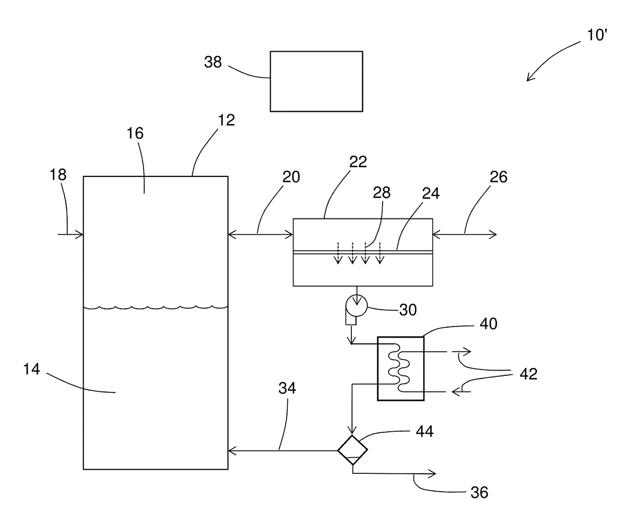
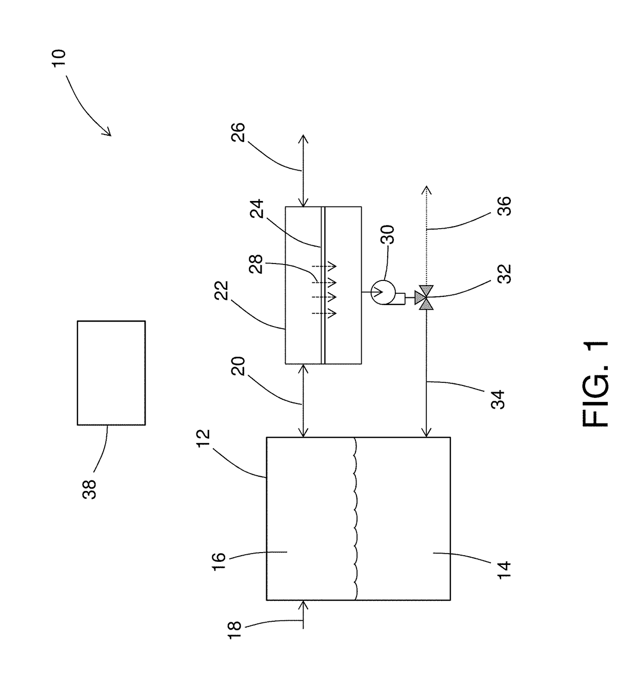
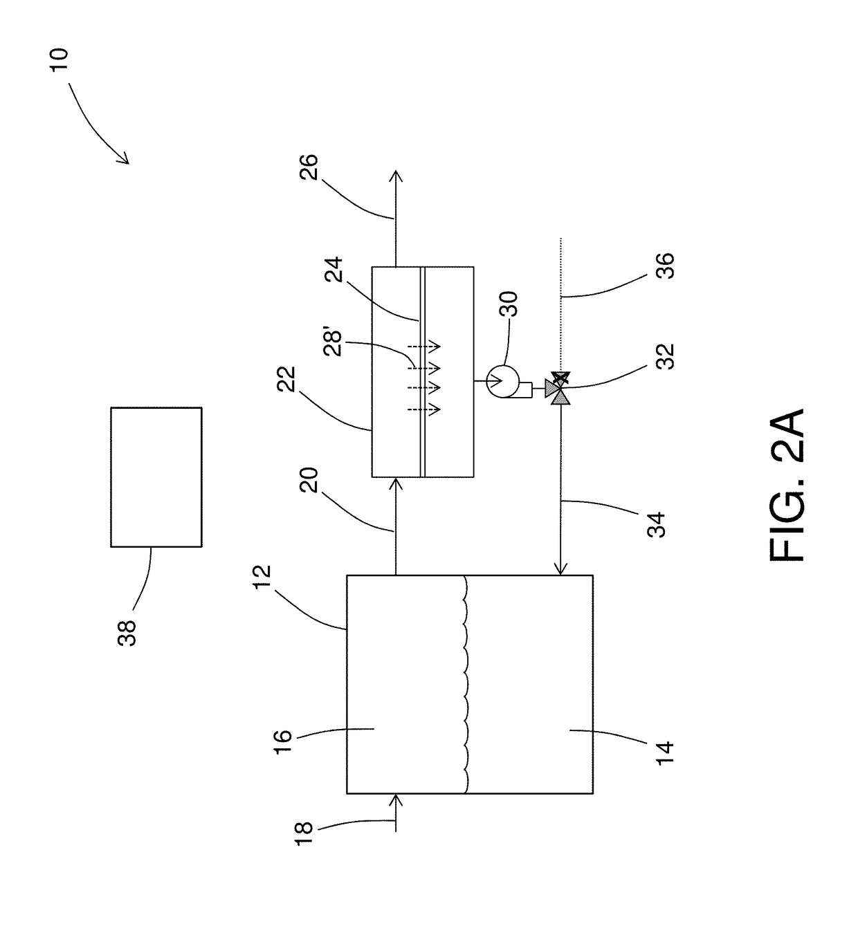
[0013]In some embodiments, the above-referenced fuel tank system can be disposed on-board a vehicle. The term “vehicle” includes any powered conveyance device, including but not limited to aircraft, marine vessels, railroad engines, or roadway motor vehicles. In some embodiments, the vehicle is an aircraft. In some embodiments, the vehicle is a marine vessel such as a marine vessel fueled by liquefied natural gas (LNG). Referring now to the Figures, in which the same numbering may be used in more than one Figure to represent the same feature without the necessity of explicit repetition in the description for each Figure, FIG. 1 schematically depicts a fuel tank system 10. In this description, a single separation membrane is shown for ease of illustration; however, the term “separation membrane” as used herein can include a plurality of separation membranes, which can be integrated into a single device or can be disposed at discrete locations along the first fluid flow path.

[0014]As ...


PUM


Abstract

A fuel tank system is disclosed that includes a fuel tank and a first fluid flow path between a gas space in the fuel tank and outside of the fuel system. A gas separation membrane is disposed with a first side in communication with the first fluid flow path and a second side in communication with a second fluid flow path. A fluid control device is in communication with the second fluid flow path and is configured to provide fluid flow from the second fluid flow path to a liquid space in the fuel tank or to outside of the fuel system. A prime mover is disposed in communication with the second fluid flow path, and is configured to move fluid on the second fluid flow path from the second side of the separation membrane to the fuel tank liquid space or to outside of the fuel system.

Description

BACKGROUND[0001]This disclosure relates to fuel tank systems, and in particular to fuel tank vapor management systems.[0002]This disclosure relates to fuel tank systems, and in particular to fuel tank vapor management systems.[0003]It is recognized that fuel vapors within fuel tanks become combustible in the presence of oxygen. An inerting system decreases the probability of combustion of flammable materials stored in a fuel tank by maintaining a chemically non-reactive or inert gas, such as nitrogen-enriched air, in the fuel tank gas space also known as ullage. Three elements are required to initiate and sustain combustion: an ignition source (e.g., heat), fuel, and oxygen. Combustion may be prevented by reducing any one of these three elements. If the presence of an ignition source cannot be prevented within a fuel tank, then the tank may be made inert by: 1) reducing the oxygen concentration, 2) reducing the fuel concentration of the ullage to below the lower explosive limit (LEL...

Claims


Application Information

Patent Timeline
IPC IPC(8): B01D53/22B01D17/02B64D37/02B64D37/32
CPCB01D53/22B64D37/32B01D2053/221B01D17/02B64D37/02B01D2259/4516B64D37/005B64F1/28Y02T50/80
Inventor RHEAUME, JONATHANCORDATOS, HARALAMBOS
Owner HAMILTON SUNDSTRAND CORP
Why Eureka
Try Eureka