
Expansion joint seal system

a technology of expansion joint and seal system, which is applied in the direction of building components, building insulations, constructions, etc., can solve the problems of requiring replacement of concrete, spalling of concrete, and insufficient protection of the surface of the construction panel perpendicular to the exposed surfa

Inactive Publication Date: 2017-12-28
SCHUL INT COMPANY
View PDF1 Cites 57 Cited by
  • Summary
  • Abstract
  • Description
  • Claims
  • Application Information

AI Technical Summary

Benefits of technology

The system effectively protects concrete substrates from spalling and structural damage during high-temperature events while maintaining flexibility and water resistance, adhering to stringent fire-rating standards like the Dutch RWS curve, and reducing the need for excessive fireproof coatings.

Problems solved by technology

These systems, however, do not provide substantive protection of surface of the construction panels perpendicular to the exposed surface against fire.
These concrete ends are not protected from the heat, which can cause spalling of the concrete and therefore require replacement of the concrete.
Spalling is well-known to be detrimental to the concrete structure, potentially precluding continued use or at requiring substantial and expensive remediation to return to service.
While this may be addressed, in part, by overlapping the surface coating and the seal, this has a negative impact on the flexibility of the joint seal.
Unfortunately, these systems have little elasticity in light of the composition of intumescent.
The body has a body width extending from the body first face to the body second face and which is greater than the first distance, thus resulting in compression of the body when imposed between the substrates.
The RWS standard, however, is written for protecting the concrete behind a fire protection board or coating and does not address expansion joints.
Prior art, which has used laminates or low compression ratios, often fail under shear, resulting in delamination of the structure.
Vertical laminations in particular are known to fail in shear.

Method used


Image

  • Expansion joint seal system
  • Expansion joint seal system
  • Expansion joint seal system

Examples


Embodiment Construction

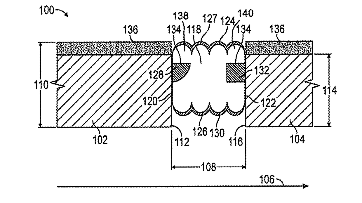
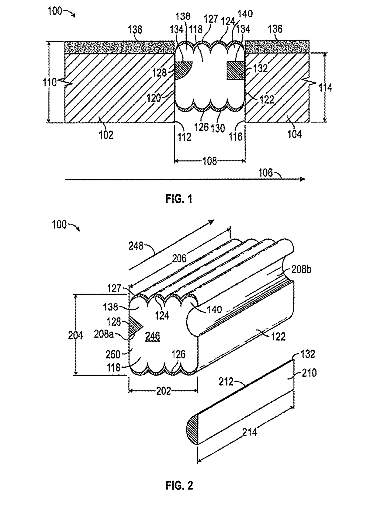
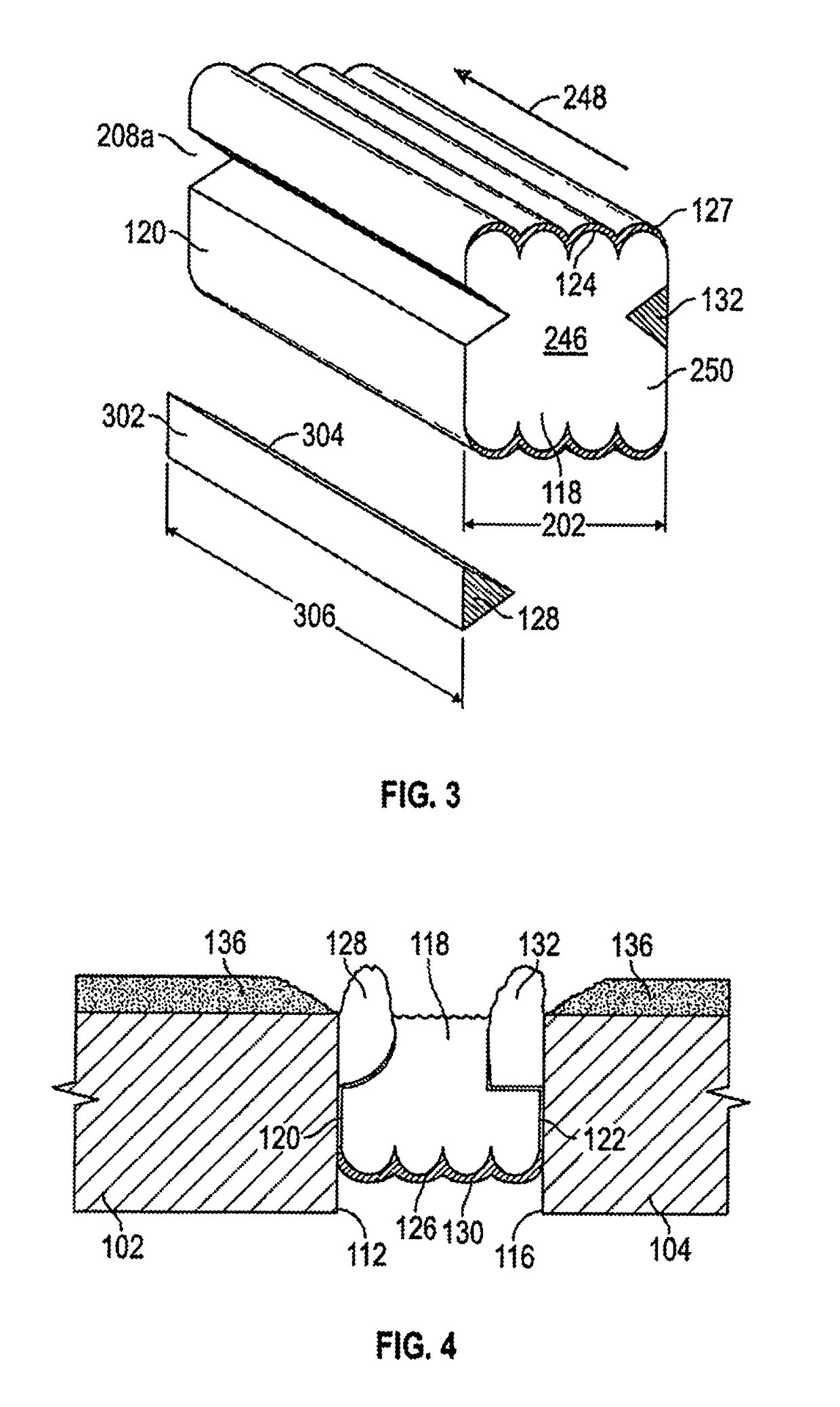
[0030]The expansion joint system 100 of the present disclosure includes a body of compressible foam 118, at least one intumescent member 128, and may include at least one elastomer layer 127 which provide an integral, but flexible, expansion joint system which has reduced susceptibility to shearing and delamination while providing fire-protection to substrate upper portions, edges and adjacent surfaces. Referring to FIGS. 1-3 and 5, the expansion joint system 100 is illustrated when imposed under compression between a first substrate 102 and a second substrate 104, typically occurring at a joint 103 between two substrates 102, 104. A side view of the expansion joint system of the present disclosure when installed between two substrates to extend above the top of the adjacent substrates is illustrated in FIG. 1. A side view of an expansion joint system of the present disclosure when installed between two substrates at an alternative location well below the top of the adjacent substra...


PUM


Abstract

An expansion joint seal system which includes intumescent to protect uncoated edges of substrates. A fire rated compressed expansion joint sealant is provided having an intumescent proximate, but below the water-resistant top of the fire-retardant foam, so that when exposed to fire, the intumescent expands to protect the exposed vertical surface of the adjacent concrete substrate. The end of the concrete is therefore protected in a manner which does not require joint overlap between the horizontal fire resistant coating and the compressible sealant.

Description

CROSS-REFERENCE TO RELATED APPLICATIONS[0001]This application is a continuation of PCT Patent Application Serial No. PCT / US16 / 19059 for “Expansion Joint Seal System”, filed Feb. 23, 2016 which is incorporated herein by reference, which is a continuation of U.S. patent application Ser. No. 14 / 643,031 for “Expansion Joint Seal System”, filed Mar. 10, 2015, now U.S. Pat. No. 9,206,596, which is incorporated herein by reference.STATEMENT REGARDING FEDERALLY SPONSORED RESEARCH OR DEVELOPMENT[0002]Not Applicable.BACKGROUNDField[0003]The present disclosure relates generally to systems for creating a durable water-resistant seal between adjacent panels subject to temperature expansion and contraction which further provides some protection for exposed surfaces against extreme heat. More particularly, the present disclosure is directed to providing an expansion joint seal system which includes intumescent to protect uncoated edges of substrates.Description of the Related Art[0004]Construction...

Claims


Application Information

Patent Timeline
Patent Type & Authority Applications(United States)
IPC IPC(8): E04B1/68E04B1/94
CPCE04B1/948E04B1/6812
Inventor ROBINSON, STEVEN R.
Owner SCHUL INT COMPANY
Learn More