Cold Atom Interferometry

a technology of cold atoms and interferometers, applied in the field ofatomic interferometers, can solve the problems of limiting system sensitivity, mechanically rigid geometries employed in single-trap designs that do not lend themselves to double-trap implementation, and the proximity of two mots in such configurations does not allow for the implementation of integral micromirror geometries

Active Publication Date: 2017-12-28
CHARLES STARK DRAPER LABORATORY
View PDF5 Cites 16 Cited by
  • Summary
  • Abstract
  • Description
  • Claims
  • Application Information

AI Technical Summary

Benefits of technology

[0021]In other embodiments of the present invention, detecting the interference fringes may include spatially resolving the interference fringes using a detector array. The methods may also include a step of feeding back the at least one of rel

Problems solved by technology

In any practical configuration, external factors bearing on the relative optical phase of successive laser beams impinging on a probed ensemble of atoms give rise to measurement perturbations and drift, ultimately limiting system sensitivity.
Mechanically rigid geometries that have been employed in single-trap designs do not lend themselves to double-trap implementation.
The proximity of two MOTs in such configurations does not allow for implementation of integral micromirror geometri

Method used


Image

  • Cold Atom Interferometry
  • Cold Atom Interferometry
  • Cold Atom Interferometry

Examples


Embodiment Construction

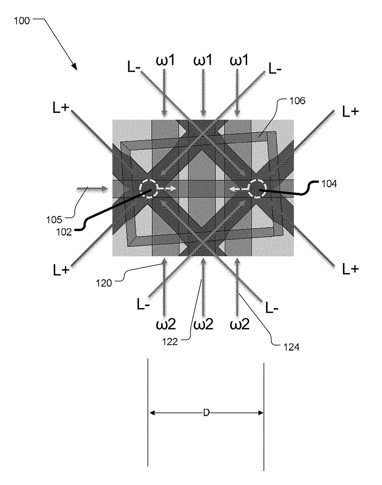
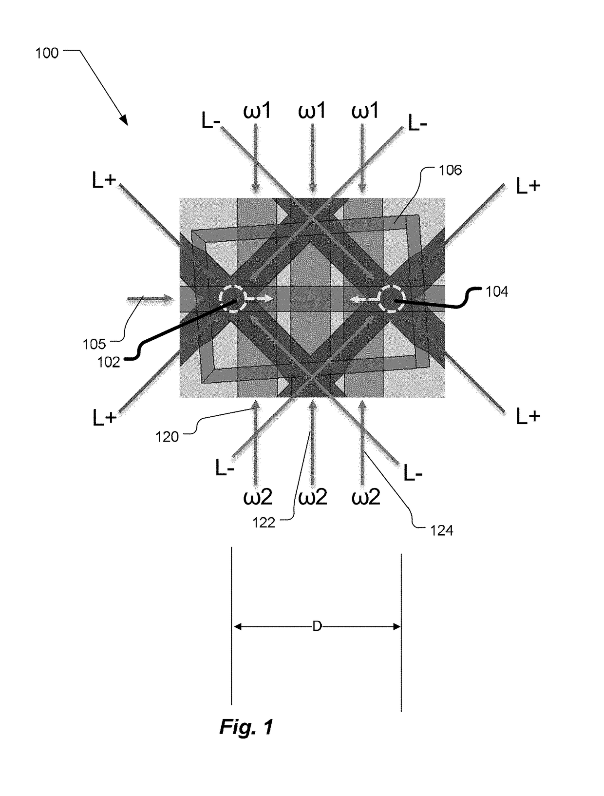
[0015]In accordance with embodiments of the present invention, an improvement is provided to measurement methods that have steps of trapping an ensemble of atoms and measuring interference fringes between populations of internal states of a quantum system based on interaction of the ensemble of atoms with a plurality of counterpropagating optical beam pairs. The improvement entails steps of:

[0016]coupling the plurality of counterpropagating beam pairs such that each pair of beams traverses the ensemble of atoms in parallel counterpropagating beam paths;

[0017]interposing a beam-splitting surface common to the plurality of counterpropagating beam pairs;

[0018]generating interference fringes between reflections of the plurality of parallel pairs of counterpropagating beams to generate a detector signal; and

[0019]processing the detector signal to derive at least one of relative phase and relative alignment between respective pairs of the counterpropagating beams.

[0020]In accordance with ...


PUM


Abstract

Improvements to atom interferometers. An improved atom interferometer has a single polarization-preserving fiber, coupled for propagation of beams of two Raman frequencies, and a parallel displacement beamsplitter for separating the laser beams into respective free-space-propagating parallel beams traversing at least one ensemble of atoms. A reflector generates one or more beams counterpropagating through the ensemble of atoms. Other improvements include interposing a beam-splitting surface common to a plurality of parallel pairs of beams counterpropagating through the ensemble of atoms, generating interference fringes between reflections of the beams to generate a detector signal; and processing the detector signal to derive at least one of relative phase and relative alignment between respective pairs of the counterpropagating beams.

Description

[0001]The present application is a continuation-in-part of U.S. Ser. No. 15 / 402,399, filed Jan. 10, 2017, and, through that application, claims the priority of U.S. Provisional Application Ser. No. 62 / 353,415, filed Jun. 22, 2016. Both of those applications are incorporated herein by reference.STATEMENT REGARDING FEDERALLY SPONSORED RESEARCH OR DEVELOPMENT[0002]This invention was made with government support under contract number FA8650-13-C-7325, awarded by the United States Air Force. The U.S. Government has certain rights in the invention.TECHNICAL FIELD[0003]The present invention relates to atomic interferometry, and, more particularly, to optical configurations that enable unprecedented precision and stability of atom interferometric measurements.BACKGROUND ART[0004]Some of the most precise measurements of physical quantities currently available derive from atom interferometry. These include limits on composition-dependent gravitational forces (Einstein's principle of equivalen...

Claims


Application Information

Patent Timeline
IPC IPC(8): G21K1/00G01B9/02G21K1/02G21K1/06
CPCG21K1/006G21K1/067G21K1/025G01B9/02015G01C19/58G01P15/08
Inventor GILL, ALEXANDERBYRNES, STEVEN J.CHOY, JENNIFERWANG, CHRISTINE Y.SINCLAIR, MATTHEW A.KELSEY, ADAMJOHNSON, DAVID
Owner CHARLES STARK DRAPER LABORATORY
Why Eureka
Try Eureka