Dielectric composition and electronic component

a technology of electronic components and dielectric compositions, applied in the direction of fixed capacitor electrodes, fixed capacitor electrodes, electrical equipment, etc., can solve the problems of difficult to obtain intended capacitance -temperature load lifetime could be improved, etc., to achieve excellent high-temperature load lifetime

Active Publication Date: 2017-12-28
TDK CORPARATION
View PDF1 Cites 1 Cited by
  • Summary
  • Abstract
  • Description
  • Claims
  • Application Information

AI Technical Summary

Benefits of technology

[0066]According to the present invention, a dielectric composition having excellent high-temperature load lifetime in high temperature atmosphere at 250° C. for automobiles and power devices using the SiC-based or GaN-based semiconductor; and an electronic component using the dielectric composition can be provided.

Problems solved by technology

However, it is not mentioned if the high-temperature load lifetime could be improved at the same time when direct voltage is applied for a long time continuously.
H10-90751 discloses that excellent high-temperature load lifetime is obtained at 200° C. However, it is difficult to obtain an intended capacitance since the obtained relative dielectric constant is low.
However, they do not mention about if the high-temperature load lifetime could be improved at the same time when direct voltage is applied for a long time continuously.

Method used


Image

  • Dielectric composition and electronic component
  • Dielectric composition and electronic component

Examples


embodiments

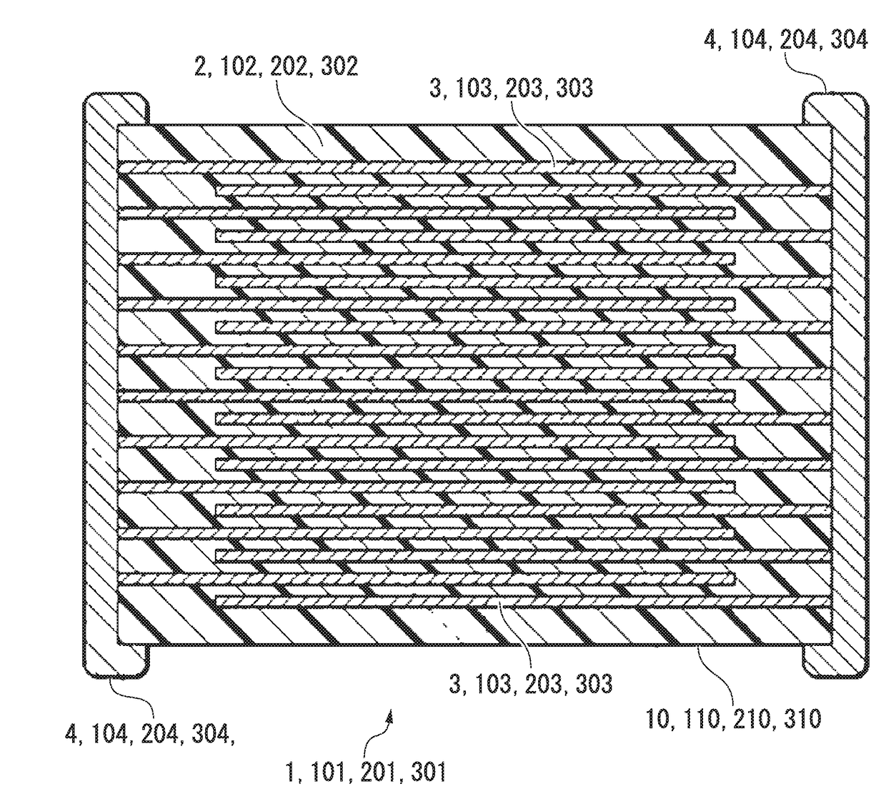
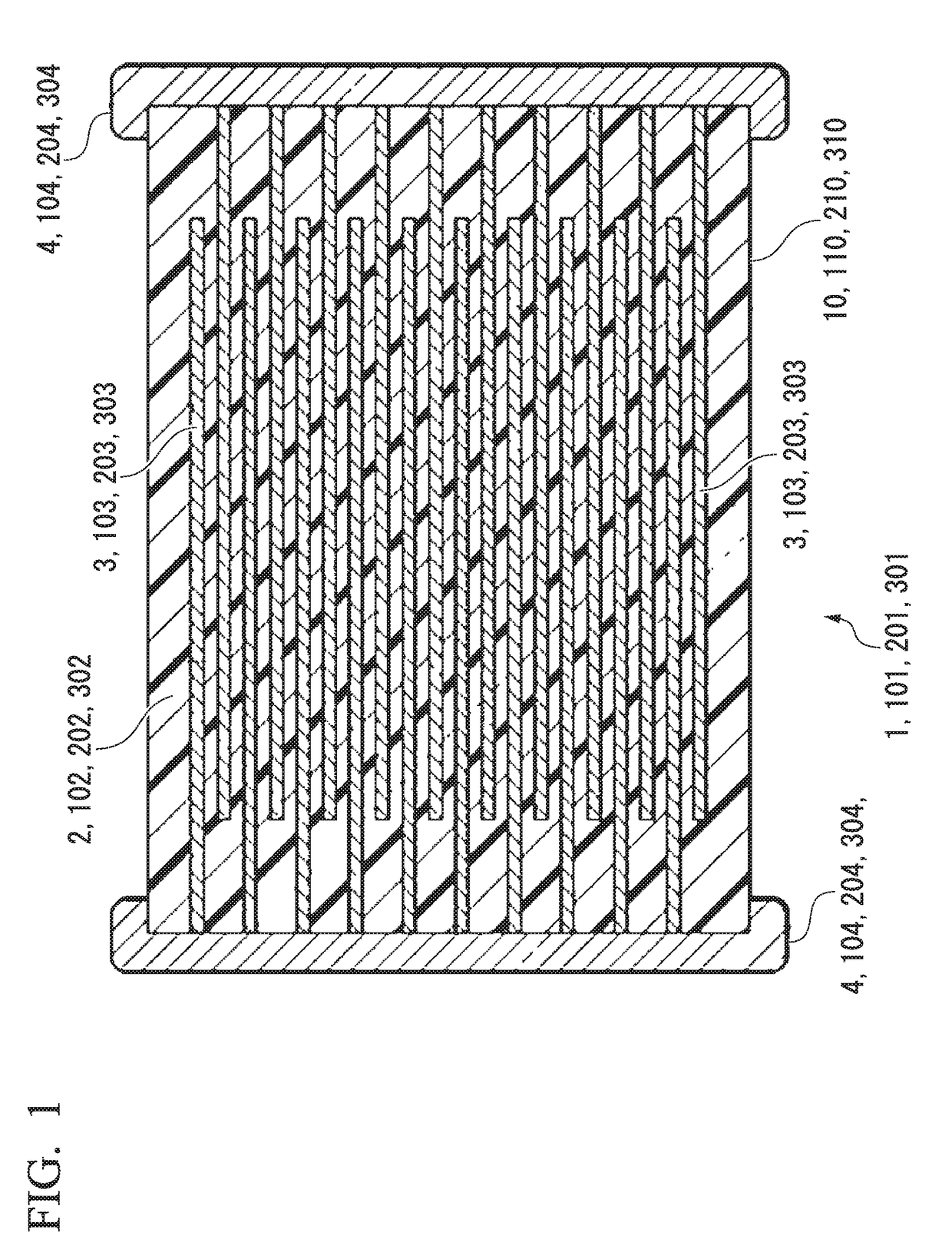
[0068]First, the multilayer ceramic capacitor, which is the main application of the dielectric composition of the present invention, will be described. The following description is a description of the same common configuration in the first to fourth embodiments described later. FIG. 1 is a cross-sectional view of a general multilayer ceramic capacitor.

[0069]The multilayer ceramic capacitors 1, 101, 201, 301 are composed of the capacitor element main bodies 10, 110, 210, 310 in which the dielectric layers 2, 102, 202, 302 and the inner electrode layers 3, 103, 203, 303 are alternately laminated. At both ends of the capacitor element main bodies 10, 110, 210, 310, a pair of the external electrodes 4, 104, 204, 304, each of which is electrically connected to the inner electrode layers 3, 103, 203, 303 alternately arranged inside the capacitor element main bodies 10, 110, 210, 310, is formed. The shapes of the capacitor element main bodies 10, 110, 210, and 310 are not particularly lim...

first embodiment

[0078]The dielectric composition according to the first embodiment is a dielectric composition having a main component represented by the chemical formula a{K(Ba1-xSrx)2Nb5O15}+b{(Ca1-ySry)(Zr1-zTiz)O3}, x, y and z satisfying 0.35≦x≦0.75, 0.01≦y≦0.25, 0.01≦z≦0.25, and the relationship between a and b in molar ratio satisfying a+b=1.00, and 0.32≦a≦0.66.

[0079]By the dielectric composition having the above-described features, a dielectric composition, which is suitable for use in the temperature range about 250° C.; has excellent high-temperature load lifetime and relatively high relative dielectric constant, can be provided. Reasons for being able to obtain these effects are explained below.

[0080]The inventors found that the effect of suppressing migration of oxygen defects, which are believed to be the reason for deterioration of the high-temperature load lifetime, can be obtained by including: a perovskite-type complex oxide represented by the chemical formula (Ca1-ySry)(Zr1-zTiz)O3...

second embodiment

[0116]Next, the dielectric composition of the second embodiment is explained in detail.

[0117]The dielectric composition according to the second embodiment is a dielectric composition having a main component represented by the chemical formula a{K(Ba1-xSrx)2Nb5O15}+b{Ba(Ti1-uZru)O3}, x and u satisfying 0.35≦x≦0.75, 0.02≦u≦0.25, and the relationship between a and b in molar ratio satisfying a+b=1.00, and 0.35≦a≦0.65.

[0118]By the dielectric composition having the above-described features, a dielectric composition, which is suitable for use in the temperature range about 250° C. and has excellent high-temperature load lifetime, can be provided. Reasons for being able to obtain these effects are explained below.

[0119]The inventors found that the effect of suppressing migration of oxygen defects, which are believed to be the reason for deterioration of the high-temperature load lifetime, can be obtained by including: a perovskite-type complex oxide represented by the chemical formula Ba(T...


PUM

PropertyMeasurementUnit
temperatureaaaaaaaaaa
capacitance-temperature characteristicsaaaaaaaaaa

Abstract

A dielectric composition is provided. The dielectric composition includes: a main component made of: a first complex oxide expressed by a chemical formula {K(Ba1-xSrx)2Nb5O15}; and a second complex oxide expressed by a chemical formula that differs the chemical formula of the first complex oxide. The second complex oxide is a complex oxide expressed by one of chemical formulae: {(Ca1-ySry)(Zr1-zTiz)O3}; {Ba(Ti1-uZru)O3}; {(Ca1-vSrv)TiSiO5}; and {(Ba1-wRe2w/3)Nb2O6}, x satisfies 0.35≦x≦0.75, and a satisfies 0.25≦a≦0.75 when a molar ratio between the first and second complex oxides is defined by a:b in an order and a+b=1.00.

Description

BACKGROUND OF THE INVENTIONField of the Invention[0001]The present invention relates to a dielectric composition, which is particularly suitable for being used in a high-temperature condition such as one for automotive use; and an electronic component in which the dielectric composition is used as a dielectric layer.[0002]Priority is claimed on: Japanese Patent Application No. 2016-127387; Japanese Patent Application No. 2016-127385; Japanese Patent Application No. 2016-127386; and Japanese Patent Application No. 2016-127384, all of which were filed on Jun. 28, 2016, the contents of which are incorporated herein by reference.Description of Related Art[0003]The laminated ceramic capacitors are mounted on many electronic devices because of their high reliability and low cost. Specific examples of electronic devices include information terminals such as cellular phones, home appliances, and automobile electrical components. Among them, in laminated ceramic capacitors used for automotiv...

Claims


Application Information

Patent Timeline
Patent Type & Authority Applications(United States)
IPC IPC(8): H01G4/12C04B35/64H01G4/30H01G4/012C04B35/626C04B35/495H01G4/248
CPCH01G4/1263C04B2235/96H01G4/30C04B35/495C04B35/6261C04B35/6264C04B35/64H01G4/248C04B2235/3201C04B2235/3215C04B2235/3213C04B2235/3255C04B2235/3249C04B2235/3234C04B2235/3224C04B2235/3225C04B2235/3227C04B2235/3229C04B2235/3454C04B2235/5436C04B2235/6567H01G4/012B32B18/00C04B35/499C04B35/62675C04B35/62685C04B35/63416C04B35/63424C04B35/6365C04B35/638C04B2235/3208C04B2235/3232C04B2235/3244C04B2235/442C04B2235/5445C04B2235/6562C04B2235/6582C04B2235/6585C04B2235/785C04B2235/786C04B2237/34C04B2237/68H01G4/1218H01G4/1236
Inventor TAKAHASHI, TETSUHIRO
Owner TDK CORPARATION
Why Eureka
Try Eureka