

Ceramic electronic device and the production method
- Summary
- Abstract
- Description
- Claims
- Application Information
AI Technical Summary
Benefits of technology
Problems solved by technology
Method used
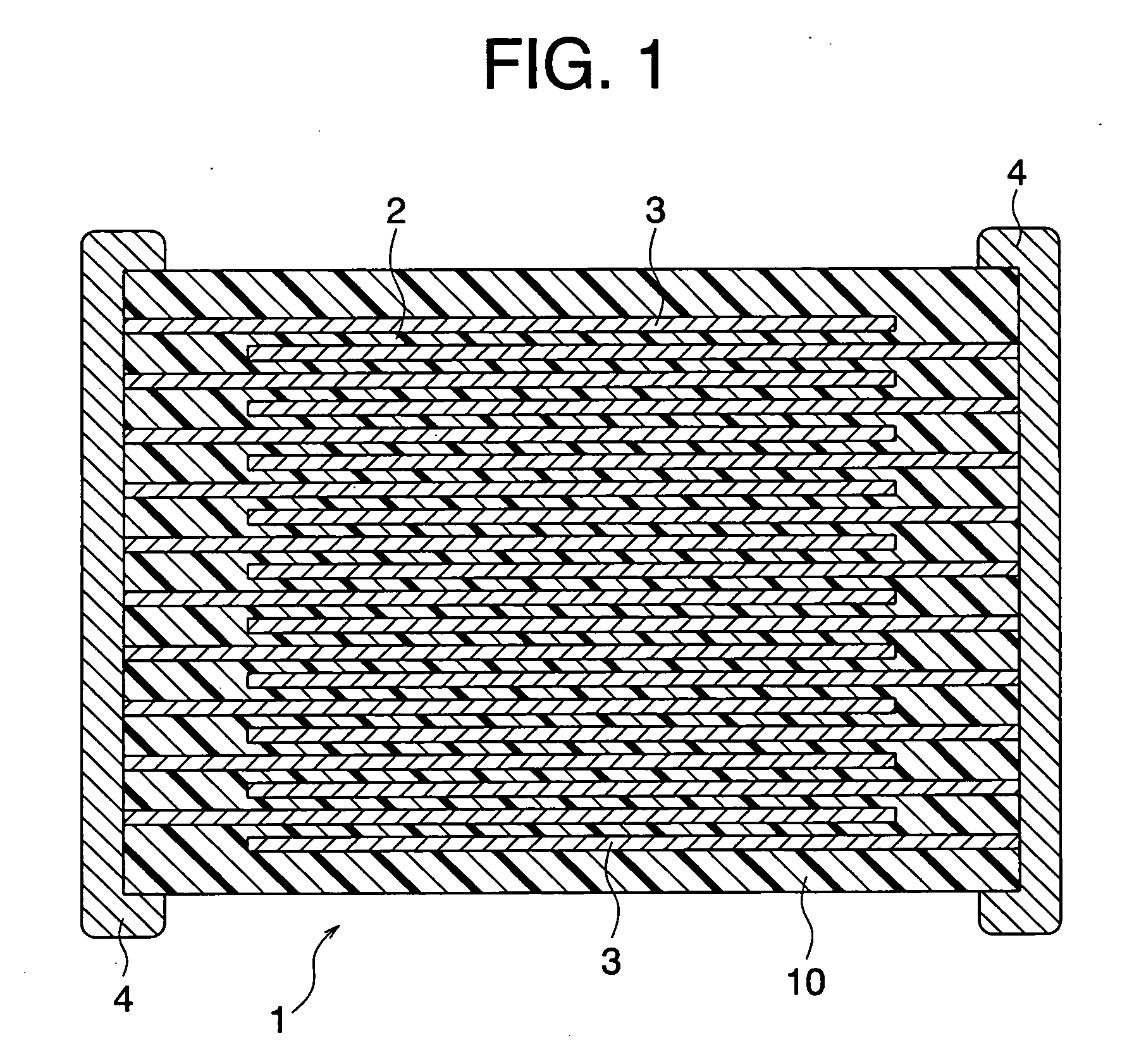
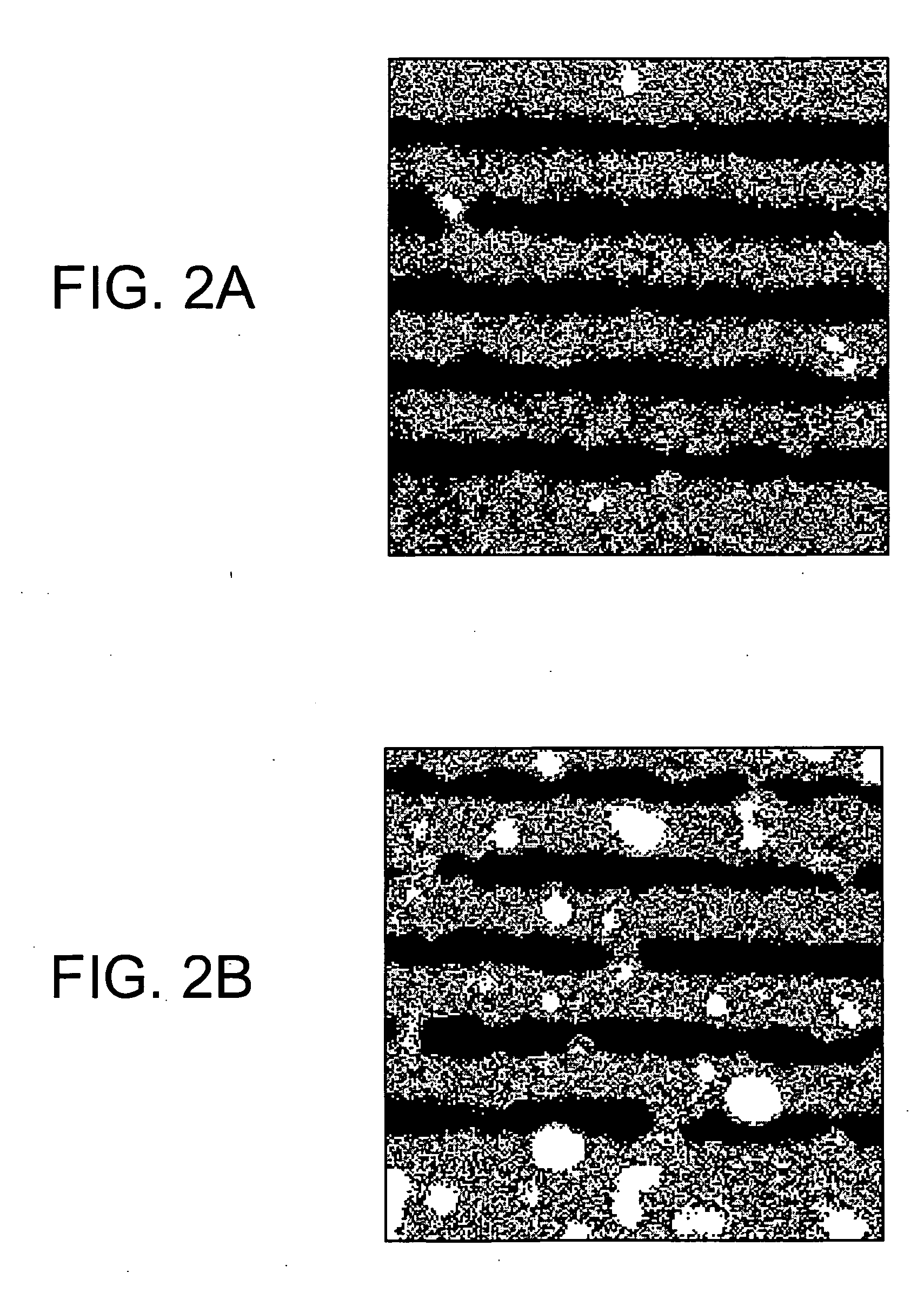
Image

Examples
example 1
[0145] First, as starting materials to produce a dielectric material, a main component material (BaTiO3) having an average particle diameter of 0.3 μm and the first to sixth subcomponent materials described below were prepared. [0146] MgO (first subcomponent): 1.0 mole [0147] (Ba0.6 Ca0.4)SiO3 (second subcomponent): 3.0 moles [0148] V2O5 (third subcomponent): 0.1 mole [0149] Y2O3 (fourth subcomponent): 2.0 moles [0150] Yb2O3 (fourth subcomponent): 1.75 moles [0151] CaZrO3 (fifth subcomponent): 1.5 moles [0152] Al2O3 (sixth subcomponent): 4.0 moles
[0153] The adding quantities of the above first to sixth subcomponents are numbers of moles with respect to 100 moles of BaTiO3 as the main component.
[0154] Next, the main component and subcomponent materials were wet mixed by a ball mill for 16 hours and dried to obtain a dielectric material. Next, 100 parts by weight of the obtained dried dielectric material, 4.8 parts by weight of an acrylic resin, 100 parts by weight of ethyl acetate,...
example 2
[0179] Other than changing an adding quantity of Al2O3 as a subcomponent to 1.0 mole with respect to 100 moles of the main component and the holding temperature at firing to 1260° C., samples 11 to 17 of the multilayer ceramic capacitor were produced in the same way as in the example 1, and measurement of the withstand voltage, high temperature load lifetime and C.V. value of Al2O3 was made in the same way as in the example 1. Note that in the samples 11 to 17 in the present example, the same Al2O3 as those in the samples 1 to 7 in the example 1 were used, respectively.
TABLE 2Al2O3AddingMaximumFiringWithstandAverageCV Value of AlSampleQuantityDiameterD50D100D100 − D50TemperatureVoltageLifetimeAfter FiringNo.[wt %][μm][μm][μm][μm][° C.][V / μm][h][%]11Reference1.020.076.8234.1157.31260806.7123Example12Example1.05.110.277.467.2126013412.367.113Example1.03.45.624.518.9126015616.850.114Example1.02.52.35.12.8126017819.148.115Example1.01.50.72.51.8126019323.142.716Example1.00.20.31.20.912...
PUM
| Property | Measurement | Unit |
|---|---|---|
| Temperature | aaaaa | aaaaa |
| Length | aaaaa | aaaaa |
| Length | aaaaa | aaaaa |
Abstract
Description
Claims
Application Information