

Dielectric ceramic composition and electronic device
- Summary
- Abstract
- Description
- Claims
- Application Information
AI Technical Summary
Benefits of technology
Problems solved by technology
Method used
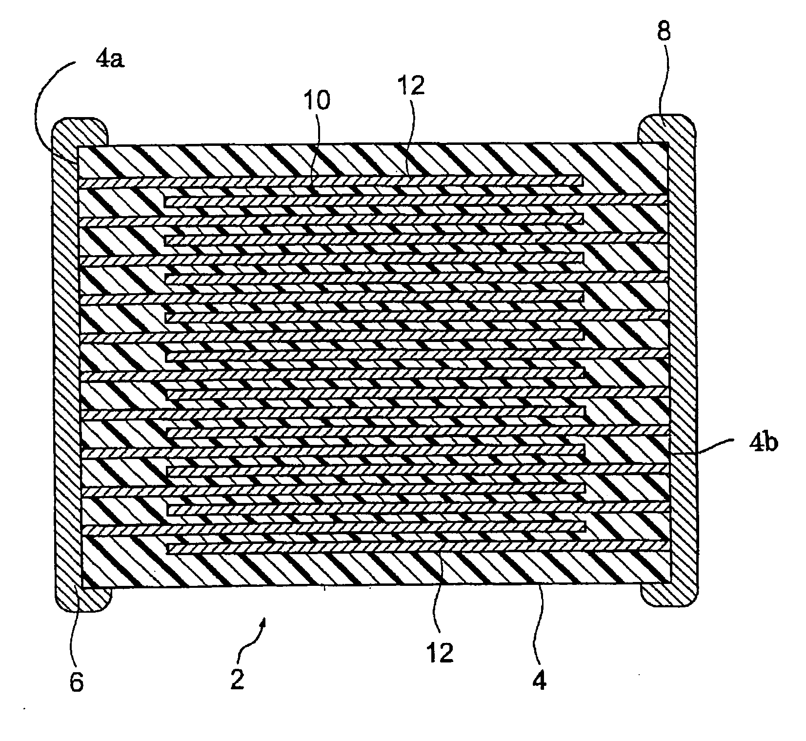
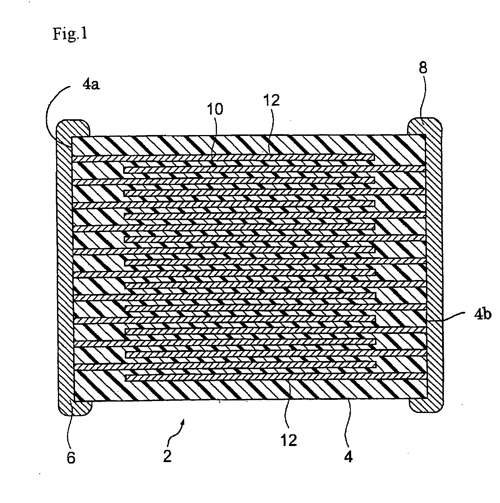
Image

Examples
example 1
[0098] First, to produce a dielectric material, BaTiO3 as the main component, the first to third subcomponents and a glass component were prepared as starting materials. An average particle diameter of the starting materials was suitably selected from a range of 0.15 to 1.0 μm, respectively. As the glass component MxSiO3, BaαCa(1-α)SiO3 was used. Note that a value of “α” was 0.58.
[0099] As a material of MgO as the first subcomponent, MgCO3 as carbonate was used, and oxides (the second subcomponent: Y2O3, the third subcomponent: V2O5 and the glass component: Ba0.58Ca0.42SiO3) were used as other materials. Note that Ba0.58Ca0.42SiO3 as the glass component was weighed to satisfy a predetermined ratio of BaCO3, CaCO3 and SiO2 and produced by wet mixing by a ball mill for 16 hours, drying, then, firing at 1150° C. in the air and, furthermore, wet grinding by a ball mill for 100 hours.
[0100] Note that as to BaTiO3 as the main component, the same characteristics were obtained also by usi...
example 2
[0130] Furthermore, samples having the same composition as that in the sample No. 7 listed as a comparative example in Table 2 in the paragraph number 0105 in the patent article 1 and dielectric particles having a changed average particle diameter were produced in the same way as in the example 1, and the characteristics were measured. Both of the compositions are in the range of the present invention. The average particle diameter of the dielectric particles are 0.40 μm in the sample described in the patent article 1 and 0.25 μm in the sample of the present example. Also, a half value width of a peak of (111) plane of the dielectric ceramic composition was measured. A measurement condition of X-ray diffraction was a voltage of 30 kV, a current of 30 mA, in a range of 2 θ=10° to 80°, a scanning speed of 1 / 16 deg / min, and an integral time of 1 sec.
[0131] In evaluations of the characteristics, a capacity-temperature change rate (ΔC / C20) and a high temperature load lifetime (accelerat...
example 3
[0137] Next, samples were produced in the same way as in the example 1 except for changing an average particle diameter of the dielectric particles to 0.25 μm and changing a composition of subcomponents of the dielectric ceramic composition to a composition shown in Table 2, and measurements were made in the same way as in the example 2. The results are shown in Table 2.
[0138] Table 2
TABLE 2Capacity-MainSpecificTemperatureHighAverageHalfCompo-FiringPermit-Change RateTempera-Sam-ParticleValuenentSubcomponentTemper-tivity(1 V / μm)ture LoadpleDiameterWidthBaTiO3MgOY2O3V2O5BaαCa(1−α)SiO3MnOCr2O3ature(1 Vrm / C. / C.20[%]LifetimeNo.[μm][Degree][mol][mol][mol][mol]α[mol][mol][mol][° C.]μm)−25° C.85° C.[hr]30.250.1351000.050.300.100.581.000.000.0011803893−5.2−5.24540.250.1351000.110.300.100.581.000.000.0011853721−4.3−6.34850.250.1351000.810.300.100.581.000.000.0012003292−3.2−7.65260.250.1351001.780.300.100.581.000.000.0012103157−1.2−8.55370.250.1351002.960.300.100.581.000.000.00121030010.3−9...
PUM
| Property | Measurement | Unit |
|---|---|---|
| Temperature | aaaaa | aaaaa |
| Temperature | aaaaa | aaaaa |
| Temperature | aaaaa | aaaaa |
Abstract
Description
Claims
Application Information