
Ceramic electronic device and the production method

a technology of ceramic electronic devices and production methods, applied in the direction of fixed capacitor dielectrics, capacitor details, etc., can solve the problems of low insulation resistance (ir), reduced dielectric layers, and oxidation of electrodes when fired in the air, and achieve excellent high temperature load lifetime, high withstand voltage, and high reliability

Active Publication Date: 2008-09-02
TDK CORPARATION
View PDF27 Cites 5 Cited by
  • Summary
  • Abstract
  • Description
  • Claims
  • Application Information

AI Technical Summary

Benefits of technology

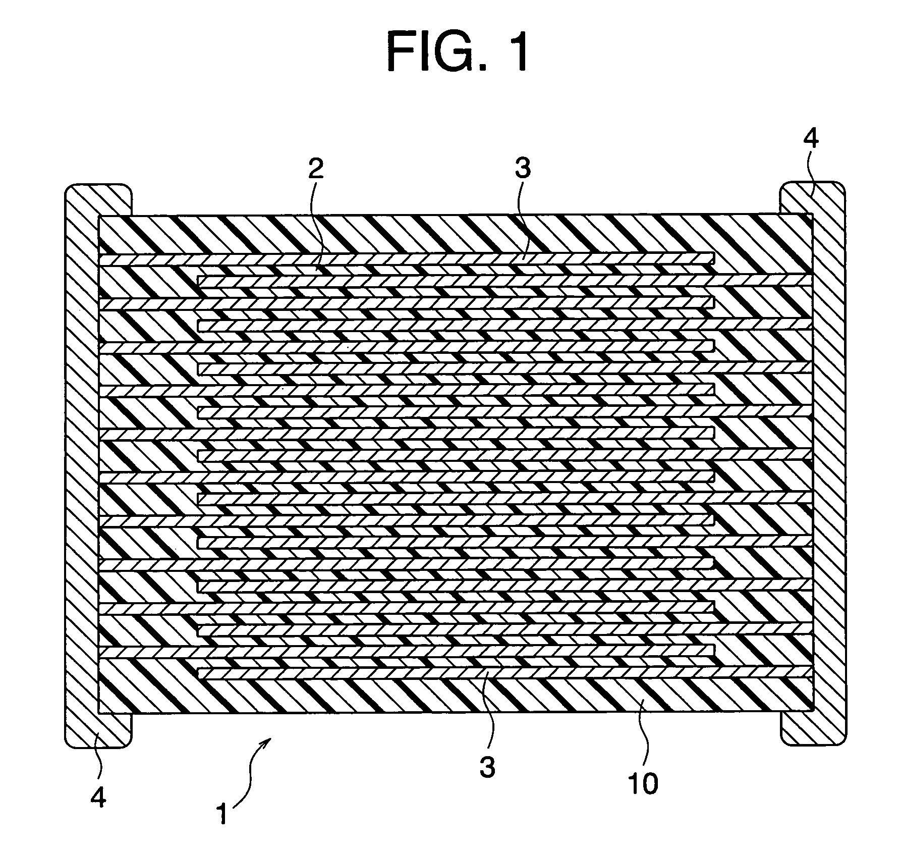
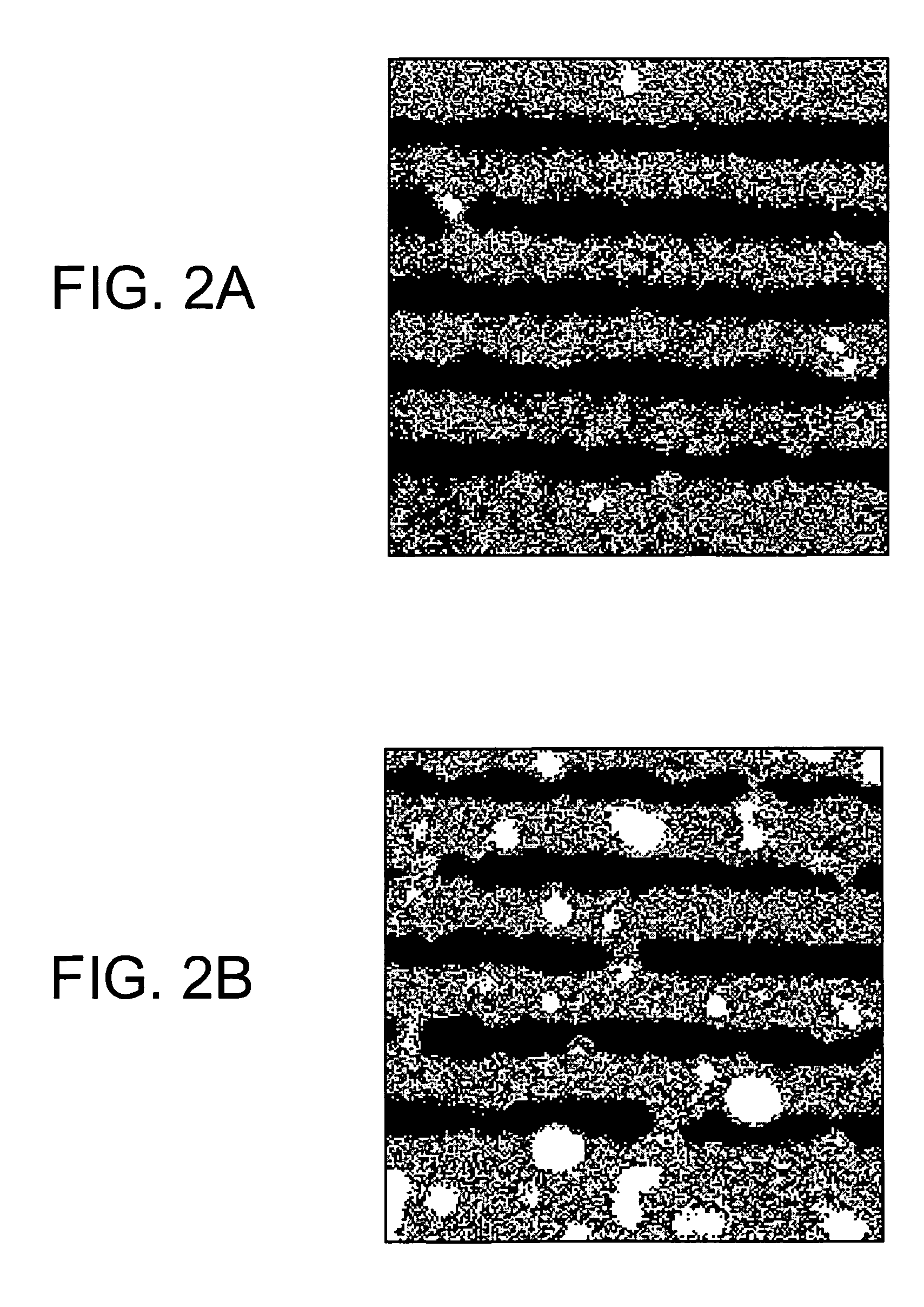
The present invention provides a highly reliable ceramic electronic device with a high withstand voltage and excellent high temperature load lifetime. This is achieved by improving the dielectric layer of the device with a specific composition and the addition of a small amount of Al oxide as a subcomponent. The dielectric layer includes a main component expressed by a composition formula of Bam TiO2+m, wherein "m" satisfies 0.995≦m≦1.010 and a ratio of Ba to Ti satisfies 0.995≦Ba / Ti≦1.010 with a segregation phase containing Al oxide. The content of Al oxide in the dielectric layer is preferably 0 to 4.0 moles in terms of Al2O3 with respect to 100 moles of the main component. The addition of Al oxide in the dielectric layer helps to improve the withstand voltage and high temperature load lifetime of the ceramic electronic device.

Problems solved by technology

When forming internal electrodes by Ni or a Ni alloy, there is a disadvantage that the electrodes are oxidized when fired in the air.
However, firing in a reducing atmosphere results in a disadvantage that the dielectric layers are reduced and the insulation resistance (IR) becomes low.
However, in the Japanese Unexamined Patent Publication No. 9-97734 and the Japanese Unexamined Patent Publication No. 10-74666, oxides included in the segregation phase were oxides of Li, Si and B, and even if a segregation phase including the oxides is formed, an effect of improving the high temperature load lifetime was insufficient.
Furthermore, there was a disadvantage that a temperature characteristic of a capacitance becomes poor and, particularly, a capacity at a high temperature becomes low in these articles.

Method used


Image

  • Ceramic electronic device and the production method
  • Ceramic electronic device and the production method

Examples


example 1

[0145]First, as starting materials to produce a dielectric material, a main component material (BaTiO3) having an average particle diameter of 0.3 μm and the first to sixth subcomponent materials described below were prepared.

[0146]MgO (first subcomponent): 1.0 mole

[0147](Ba0.6 Ca0.4)SiO3 (second subcomponent): 3.0 moles

[0148]V2O5 (third subcomponent): 0.1 mole

[0149]Y2O3 (fourth subcomponent): 2.0 moles

[0150]Yb2O3 (fourth subcomponent): 1.75 moles

[0151]CaZrO3 (fifth subcomponent): 1.5 moles

[0152]Al2O3 (sixth subcomponent): 4.0 moles

[0153]The adding quantities of the above first to sixth subcomponents are numbers of moles with respect to 100 moles of BaTiO3 as the main component.

[0154]Next, the main component and subcomponent materials were wet mixed by a ball mill for 16 hours and dried to obtain a dielectric material. Next, 100 parts by weight of the obtained dried dielectric material, 4.8 parts by weight of an acrylic resin, 100 parts by weight of ethyl acetate, 6 parts by weight ...

example 2

[0180]Other than changing an adding quantity of Al2O3 as a subcomponent to 1.0 mole with respect to 100 moles of the main component and the holding temperature at firing to 1260° C., samples 11 to 17 of the multilayer ceramic capacitor were produced in the same way as in the example 1, and measurement of the withstand voltage, high temperature load lifetime and C.V. value of Al2O3 was made in the same way as in the example 1. Note that in the samples 11 to 17 in the present example, the same Al2O3 as those in the samples 1 to 7 in the example 1 were used, respectively.

[0181]

TABLE 2Al2O3AddingMaximumFiringWithstandCV Value of AlSampleQuantityDiameterD50D100D100-D50TemperatureVoltageAverageAfter FiringNo.mol.[μm][μm][μm][μm][° C.][V / μm]Lifetime[%]11Reference1.020.076.8234.1157.31260806.7123Example12Example1.05.110.277.467.2126013412.367.113Example1.03.45.624.518.9126015616.850.114Example1.02.52.35.12.8126017819.148.115Example1.01.50.72.51.8126019323.142.716Example1.00.20.31.20.9126021...


PUM

PropertyMeasurementUnit
particle diameteraaaaaaaaaa
equivalent diameteraaaaaaaaaa
diameteraaaaaaaaaa

Abstract

A ceramic electronic device including a dielectric layer, wherein the dielectric layer includes a main component expressed by a composition formula of Bam TiO2+m, wherein “m” satisfies 0.995≦m≦1.010 and a ratio of Ba and Ti satisfies 0.995≦Ba / Ti≦1.010, and a subcomponent (a sixth subcomponent) including an oxide of Al; and a content of the Al compound is 0 to 4.0 moles (note that 0 is not included) in terms of Al2O3 with respect to 100 moles of the main component; and preferably, the dielectric layer includes a segregation phase, and the segregation phase includes an oxide of Al.

Description

BACKGROUND OF THE INVENTION[0001]1. Field of the Invention[0002]The present invention relates to a ceramic electronic device, such as a multilayer ceramic capacitor, and the production method, and particularly relates to a highly reliable ceramic electronic device having a high withstand voltage and an excellent high temperature load lifetime and the production method.[0003]2. Description of the Related Art[0004]A multilayer ceramic capacitor is widely used as a highly reliable compact electronic device having a large capacity, and the number to be used in an electric apparatus and an electronic apparatus is also large. In recent years, as apparatuses becoming more compact with higher performance, demands for a multilayer ceramic capacitor to be more compact, larger in capacity, lower in price, and higher in reliability have increasingly become stronger.[0005]A multilayer ceramic capacitor is normally produced by stacking an internal electrode paste and dielectric slurry (paste) by ...

Claims


Application Information

Patent Timeline
Patent Type & Authority Patents(United States)
IPC IPC(8): C04B35/468
CPCH01G4/10C04B35/46H01G4/12
Inventor ITO, KAZUSHIGESATO, AKIRA
Owner TDK CORPARATION
Learn More