Collimator

a collimator and collimator technology, applied in the field of collimators and nuclear medicine, can solve the problems of reducing affecting the scan time, and weighing hundreds of kilograms of the gantry including the positioning mechanism of the detector head, so as to reduce the spatial resolution of the detector unit

Active Publication Date: 2018-01-04
SPECTRUM DYNAMICS MEDICAL LTD
View PDF0 Cites 11 Cited by
  • Summary
  • Abstract
  • Description
  • Claims
  • Application Information

AI Technical Summary

Benefits of technology

[0064]According to some embodiments, the detector positioning arrangement is operable to orient the detector heads angularly to prevent interference between adjacent detector heads when the detector heads are extended to a desired position.
[0088]According to an aspect of some embodiments of the invention, there is provided a detector unit for a Nuclear Medicine (NM) imaging system having a detector element responsive to gamma ray photons to provide an electrical output signal and a collimator formed of first and second sets of septa extending in two directions that intersect to define an array of collimator cells, in which the septa are moveable to change the geometry of the collimator to increase and decrease the spatial resolution of the detector unit.
[0123]According to an aspect of some embodiments of the invention, there is provided a collimator for attachment to a Nuclear Medicine (NM) imaging system detector element responsive to gamma ray photons to provide an electrical output signal, formed by first and second sets of septa extending in two directions that intersect to define an array of collimator cells, in which the septa are moveable to change the geometry of the collimator to increase and decrease the spatial resolution of the detector unit.
[0139]According to some embodiments, there is provided an N-M tomography system in which the detector heads are formed by a detector element responsive to gamma ray photons to provide an electrical output signal and a collimator having first and second sets of septa extending in two directions that intersect to define an array of collimator cells that septa are moveable to change the geometry of the collimator to increase and decrease the spatial resolution of the detector unit.

Problems solved by technology

However, a typical gantry installation including detector head positioning mechanisms can weigh hundreds of kilograms, and repositioning the gantry between images can require several minutes.
This can be a significant factor in the time required for a scan.
Possibly due to the lower efficiency and prolonged acquisition time, fixed-diameter rotating-only partly populated gantries have not been adopted commercially.
These isotopes have very short half-lives, i.e. they decay quite rapidly, and often cannot practically be used if produced off-site at a distant facility.
Isotopes used in PET imaging typically have short half-lives (i.e., exhibit rapid decay).
This limits the sensitivity of the camera system, thereby increasing the time required to obtain sufficient data for a good image.
For example, PET systems have historically provided better spatial resolution and faster examination, but are generally much more expensive than SPECT systems, mainly due to the large number of detector elements needed to fully populate the gantry, and the complex coincidence circuitry, but also partially due to the fact that the cyclotron itself is costly and requires high-level technical support.
However, despite technological advances, conventional SPECT systems still provide lower resolution images than PET systems, and consequently, the SPECT images are generally less detailed than PET images due at least in part to scatter and attenuation of the lower energy of the photons.
A SPECT scan also typically takes longer than a PET scan, and requires a patient not to move for a longer time, or even to be immobilized and limits the ability to visualize rapid functional changes.
Further, since SPECT detectors generally require collimators, there is an inherent tradeoff between resolution and sensitivity.
Another limitation of conventional N-M tomography systems, especially PET systems, is that reducing the number of detector heads to avoid the high cost of fully populating the gantry ring as in U.S. Pat. No. 6,137,109 and in Cherry et al. mentioned above sometimes results in reduced spatial resolution and / or longer scan times for scans of small ROIs in systems having a bore size large enough to accommodate obese patients.
This limitation is often addressed by the purchase of separate systems for examining patients of large girth and for examining small ROIs.
Yet a further issue concerns the high initial cost of an N-M tomography system.
Often, a customer has a limited budget or limited needs which results in purchase of a system having limited capability.
However, as financial resources or needs change, an entirely new system may need to be purchased.

Method used


Image

  • Collimator
  • Collimator
  • Collimator

Examples


example

[0502]FIGS. 23A-23C illustrate qualitatively the result of a simulation study performed on an exemplary collimated detector as described herein formed of 0.2 mm tungsten septa. In FIG. 23A, the horizontal axis represents ±θ, the angle between an approach path 2302 from an emission event 2303 off the centerline 2304 of a collimator cell 2306 (see FIG. 23B), two curves are shown: curve 2308 for a typical SPECT isotope, and 2310 for a typical PET isotope. As may be seen, SPECT performance is very directional, but for small values of θ, PET performance is comparable.

[0503]However, for PET isotopes, off-axis detection is reduced, but not by so much as to prevent use of collimated detectors according to some embodiments hereof for selectable or simultaneous SPECT and PET imaging.

[0504]FIG. 23C provides an understanding of the saw-tooth shape of the off axis detection probability for PET imaging. Here, it may be seen that the path 2310 for an emission event at some off-axis position 2308 m...


PUM


Abstract

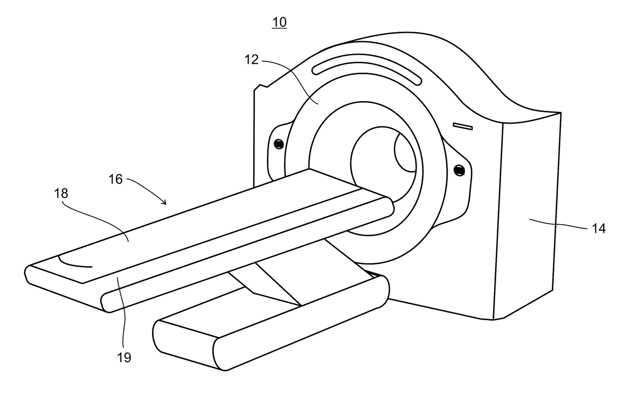
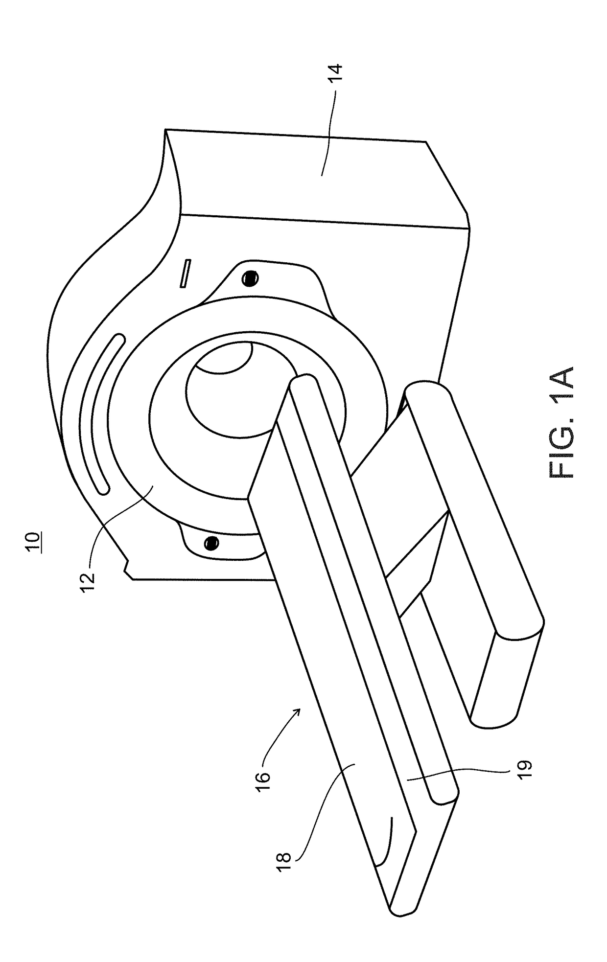
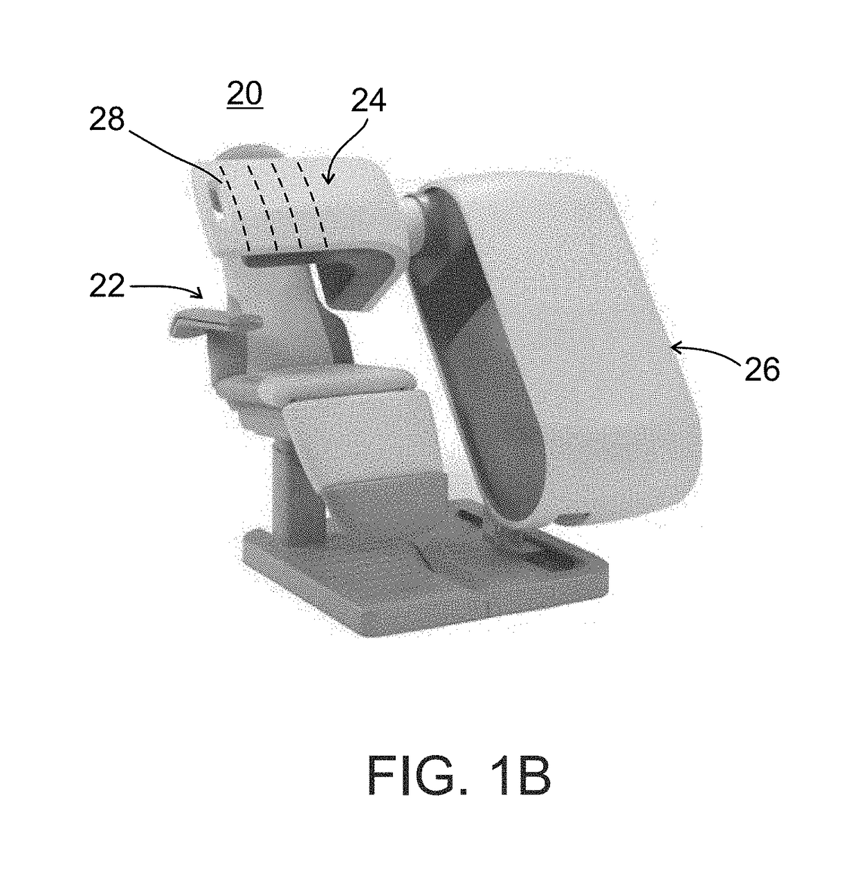
An N-M tomography system comprising: a carrier for the subject of an examination procedure; a plurality of detector heads; a carrier for the detector heads; and a detector positioning arrangement operable to position the detector heads during performance of a scan without interference or collision between adjacent detector heads to establish a variable bore size and configuration for the examination. Additionally, collimated detectors providing variable spatial resolution for SPECT imaging and which can also be used for PET imaging, whereby one set of detectors can be selectably used for either modality, or for both simultaneously.

Description

CROSS REFERENCE TO RELATED APPLICATIONS[0001]This application is a division of U.S. patent application Ser. No. 14 / 399,975 filed on Nov. 10, 2014, which is a National Phase of PCT Patent Application No. PCT / IB2013 / 053721 having International Filing Date of May 8, 2013, which is a continuation in part of, and claims the benefit of priority under 35 USC 119(e) of U.S. Provisional Patent Application No. 61 / 644,120 filed on May 8, 2012, U.S. Provisional Patent Application No. 61 / 646,333 filed on May 13, 2012, and U.S. Provisional Patent Application No. 61 / 788,394 filed on Mar. 15, 2013. The contents of the above applications are all incorporated by reference as if fully set forth in their entirety.FIELD OF THE INVENTION[0002]The present invention, in some of its embodiments, relates to apparatus and methods of tomography in the field of nuclear medicine (sometimes referred to herein as “N-M tomography”), and more particularly to N-M tomography systems as a whole, collimated detector con...

Claims


Application Information

Patent Timeline
Patent Type & Authority Applications(United States)
IPC IPC(8): A61B6/03G01T1/16A61B6/04G21K1/02A61B6/00A61B6/10
CPCA61B6/4429A61B6/102A61B6/5205G21K1/025A61B6/4291A61B6/4266A61B6/0407A61B6/4258A61B6/4417A61B6/4494A61B6/4275G01T1/1603A61B6/037A61B6/447A61B6/544A61B6/547A61B6/105A61B6/589
Inventor ROTH, NATHANIELZILBERSTIEN, YOELBEN-HAIM, SHLOMOROUSSO, BENNY
Owner SPECTRUM DYNAMICS MEDICAL LTD
Why Eureka
Try Eureka